Home
Vita
Portfolio
Glossary
Training
Home
Vita
Portfolio
Glossary
Training
PORTFOLIO
Diagrams have been redacted & modified to protect customer IP.


Islands of Automation
Problem: Because we know about Industry 4.0 and the media is constantly talking about one could easily assume that most plants are at the 4.0 level or are very close to being there. Reality is actually very far from that. Many plant are still in the middle of to 2.0 to 3.0 transition. Some plants have sections that are still in the 1.0 to 2.0 transition. These transitions are taking a lot longer than expected for many different reasons. Selling automation into a plant in many cases will have to be done in smaller steps. Most importantly interconnected automation carries with it a high cybersecurity threat. Plant staff already have a hard enough time wrapping their heads around the automation part and just cannot handle the additional load and cost of managing the cybersecurity part.
Solution:
Safe islands of automation are one possible next step solution to many plants struggling to make all the modernization transitions before them.
Physical isolation from any network outside the island is the simplest way to manage cybersecurity while one is grappling with everything else.
It is just unrealistic to expect plant staff to make all the changes at once.
Centralized data collection has a very high ROI as implementing it is far easier than centralized control.
Data can securely be transmitted one way from an island to the plant SCADA using data diodes.
Forcing any and all EMON's and wireless devices (usually already included in equipment by OEMs) inside an island to go through
the front office IT security system keeps the islands safer and is stable over the long term.
For many of our customers, even the very biggest ones, islands of automation was going to be the best we could get them to transition to
for the next few years. Islands of automation are still much better than where they are today.
Explaining the concept needed a diagram, but also one that addressed the cybersecurity concerns decision makers were having.
I used the diagrams from the Department of Homeland Security's trusted and recognizable "Recommended Practice: Improving Industrial Control
System Cybersecurity with Defense-in-Depth Strategies" as a foundation to build the Islands of automation diagram upon.
Since their documents are so well recognized by our customers, I also kept the color scheme for a consistent format to ease understanding.
For this diagram, I found that MicroSoft PowerPoint was better suited than MicroSoft Visio. For some reason, arrows are much easier draw and control in
PowerPoint and this diagram needed a lot of fine arrows.

Factory Planning
Problem: The converting customer was unaware of all the additional equipment that would be needed to meet their goals of a high quality (clean) product that would be produced in large quantities using proven conventional automation that would drive cost down.
Solution: With MicroSoft Visio I created this block diagram to show most of the equipment that would likely be needed to have a production line work at scale. Using my experience with high volume food production processes which have a lot of the same sanitary requirements, I was able to identify the appropriate packaging equipment. Drawing upon my experience with high volume plastics based automotive parts, I was able to predict the material handling and fire safety issues and initiate a planning foundation to address them early on before changes would become very expensive.

SMT Advice
Problem: Some associates in another city inadvertently ordered a surface mount chip sensor for making a prototype air quality sensor. Being software programmers they were completely unfamiliar with SMT and a loss for how to proceed. Attempts were made to verbally explain what was needed in a conference call, but failed to be understood leading to confusion and frustration.
Solution: This quick diagram was made to show what each assembly step would look like and to alert them about the specific details that are need to make the project successful the first time around. This diagram got the message across in seconds where many words on the call had not succeeded.

Developing New Business
Problem:
An overseas drafting firm wanted to expand their customer base into North America and California in particular.
They are a SolidWorks shop and had the capacity to handle more work. Unfortunately, they were coming very late into a market
that was already saturated with outsourced providers. By this time even small firms had already established relationships with
overseas low cost region drafting providers. Having experience managing an outsourced drafting team for many years, I knew what the main
problems were going to be. Fortunately, I had a long term working relationship with their in-country agent. However, we needed
to find a viable niche where we could specialize and offer a needed technical service not normally provided by outsourced firms
but where a majority of the billable hours would still be drafting related.
Opportunity:
A quality engineering friend I have known for decades was lamenting to me about all the problems
his new non-woven fabric converting client was having getting a new line set up for an innovative product they had designed.
It did not take long for me to see that there were ways by which my overseas engineering drafting client could help my friend's convertor client.
Even better was that my friend had regular communication with the CEO of the client. Any proposal I would make on behalf of my client would be
able to be presented directly to the decision maker by a trusted channel. Opportunities like that are not too frequent.
Process:
By interviewing my friend and my client in depth, doing online searching and recalling my past experiences
in similar production situations, I was able to create a FreePlane mind map showing what service could be offered and how
that could be done with the resources available between us.
Solution:
The general ideas was to create a digital twin of of what the factory could be and then move things around until we found a
layout that pleased everybody (especially city building inspectors). Typical outsourced drafting services do not do this
kind of work. I felt that once I explained what the constraints were to my client that they, as trained mechanical engineers,
could handle doing the modeling and constraint optimization services. Calculating material weights for loading trucks and
pallet racks is not hard once you know what the purpose is. The same thing would be true for the fuel load under sprinklers.
In the end any drawings we did would also have to be reviewed and approved by a licensed professional engineer. All we were doing
was the clerical work in the low cost region to reduce the overall cost of California professional services. The job still
was mostly SolidWorks modeling but with some engineering extras that could make us competitive.

Quote Conversion
Problem: One of our system integrators had a very low rate of conversion from quote into purchase orders. A lot of effort is put into each quote because integration is rarely a standard service offering. Customers very much need the integration service which is why they contact us, but somehow many never see the benefit in what we were specifically offering in the quote. Our other integrators had similar but not as severe a problem. If we could find ways to increase the conversion rate, significant profits would result from that effort.
Process:
Using a FreePlane mind map, I first identified the specific complaints we got back from customers who
declined a quote. I then identified most of the root causes of each complaint. We then brainstormed several mechanisms
by which we might be able to affect this issue without having to change the existing quotation process.
Solution:
The assessment idea was able to be tried almost immediately and has generated some additional revenue by itself.
However the it will take some time to determine if it can actually affect quote conversion.
The Glossary
idea is now ready to start using. New terms will be added as needed. The other ideas need more programming skills that
I am in the process of learning and are still in development. The skills and development work is reusable for other
applications and not tied to one firm or specific vertical market.

Explaining Differentiation
Problem:
Our manufacturers representative firm wanted to show how they successfully managed their suppliers on
behalf of their customers in many typical circumstances.
This process is their key differentiator and is quite different than the usual rep process.
A diagram was needed to show all the checks and balances used to maintain customer satisfaction because
the complexity and interrelationships between the steps were very difficult to explain with just words.
Solution:
I chose to use a process flow diagram (PFD).
It illustrates a process by showing the sequence of steps with each step depicted by a symbol, picture or text block.
Arrows indicate the order of each step.
The diagram was created in MicroSoft Visio and exported as an SVG for use in a webpage.
SVG or Scalable Vector Graphics are best for a web application as they load fast and can be read clearly at any magnification.
Animating Process Logs
Problem: A customer lost an unusually large batch of ice cream due to microbial contamination. A lot of questions were made about what exactly happened. There were several data logs, some manual and some computer generated. Consuming them in their tabular format of thousands of line entries was not easy for the team.
Process:
I made a base diagram of the key components involved in Visio.
I then forensically identified log entries where something significant changed.
For each notable change, using Visio I illustrated the base diagram to show the state it changed to and add the time stamp.
There were 36 events of note so 36 diagrams were made.
By animating the 36 diagrams into a GIF sequence using Adobe Premier Pro it was much easier to see what was happening.
Solution:
It also clearly showed where manual entries conflicted with more accurate computer generated log entries.
Some entries would have overfilled tanks way beyond their capacity.
That did not happen so the manual data became suspect.
The diagrams stopped fabricated data from deflecting attention away from the real root cause.

Turning Low Tech into High Tech
Problem:
An offshore supplier of inflatable seals wanted to get business in high-tech Silicon Valley.
Inflatable seals make good grippers for robot end effectors as they easily conform to irregular shaped objects.
We needed something simple but innovative to offer prospective customers to differentiate their products from
more established American suppliers
Solution:
I suggested using their ability to overmold the seals around printed circuit boards or flex circuits.
This quick conceptual diagram was made to show that an array of strain gauges could be laid out such that the forces on the surface of the seal
could be approximately measured in many locations so that edges and contours of object being gripped could be determined.
The idea was to make sensor embedded inflatable seals as "skin & muscles fingers" that could slip over the metal "bones" of a gripper.
It would have been up to the customer to design the actual circuit.
The supplier's job was to show that they could could make cost effective seals around circuits without leaks or rubber delamination.

Mind Map for Failure Analysis
Problem:
A customer lost an unusually large batch of ice cream due to microbial contamination.
A lot of finger pointing happened but no methodical effort was being made to identify the root cause and prevent it from happening again.
Solution:
With some of the more reasonable stakeholders I did some brainstorming and came up with this mind map using FreePlane.
It set the stage for more fact base discussions.


From Just Two Pictures
Problem: My favorite sales guy was excited about a new relationship he had developed with a local OEM. However. He was kind of worried because when he looked at the website he did not see any opportunities for our products. As an applications engineer, I take that as a personal challenge.
Solution: I looked at the website and quickly understood my guy's challenge. The OEM had just one main product and it looked mostly mechanical. But, we sold mostly electrical. Except that the line between electrical and mechanical is rather fuzzy. For example, conduit is considered an electrical part, but it is also fundamentally just tubing and our conduit line also produced all kinds of other metal tubing. Using my knowledge of our lines I was able to use just two pictures from the customer's website to show my sales guy and his customer that there was ample opportunity for us to serve this OEM.


Opportunities Hidden in Corners
Problem:
My favorite sales guy brought home electrical drawing for an opportunity at a building construction
project. It was full of switchgear which our top line, Schneider Electric, has the leading Square D brand.
Unfortunately for us, switchgear is a high profit item that Schneider likes to keep for themselves. The sales guy was rather
disappointed as he had done all the work to get a shot at the business only to find that there was nothing there for him to sell.
Solution:
With hundreds of lines and tens of thousands of SKUs it is very hard for our non-technical salespeople to
match opportunities with potential products to propose. That is where an applications engineer comes in. After carefully
studying the drawings for a while, I noticed off in a small corner of one of the sheets the grounding schematic.
This part of an electrical systems is often overlooked because it is not physically big and each part is usually rather low dollar.
But, copper is not cheap and grounding parts are almost all copper, and there are many parts to a grounding systems spread
all around a building project. All the little copper pieces add up to a significant purchase order if you can get it.
I paired up the grounding schematic with some documentation from some of our other lines that are top
brands in grounding to show my sales guy that he still had a shot at getting some decent business from his well
done relationship building efforts.

Teaching True Service
Problem: My favorite salesperson came back from a customer visit where our PLC specialists quoted a ridiculously high price to repair a metal shear by replacing the PLC controller. The customer got sticker shock and the relationship he had taken so long to cultivate was significantly damaged. The pictures he shared with me showed that the shear was leaking hydraulic fluid into a big puddle on the floor and the motor contactors and other components inside the electrical control panel were slathered with a mixture of hydraulic oil, dust and metal shavings. My guy was totally upset with the situation and was quite demoralized.
Solution:
My guy was non-technical, so I had to first explain that a new PLC would never be able to fix the machine's operational behavior until the hydraulic
leak was fixed and the electrical panel was cleaned. The dirty electrical panel was causing intermittent faults that are near impossible to permanently
repair without removing the goo that was causing them. It was highly likely the by fixing the machine hydraulics and electrics that the
existing PLC would go back to working acceptably.
He needed to advise his customer to fix the low-level foundational problems with the machine
before addressing the PLC. The PLC was most probably "misbehaving" because it was trying to control a machine with random behavior due to all
the lower system problems. By helping the customer find a real solution to their problem he could regain their trust and gather plenty other
business from them.
To make the point memorable I used MicroSoft PowerPoint to create a humorous graphic that summarized the situation using several common
metaphors: an iceberg representing unseen problems; primitive thugs solving problems with brute force, and the wise god Neptune who sees all
that happens below the surface.

Enhancing Existing Processes
Problem: A system integrator was considering using our sales team. They had their own process for managing a project. We wanted to show how our team could work with that process and also enhance it with the knowledge of customer needs we had acquired over time.
Solution: I used MicroSoft PowerPoint to show where we had found customer issues with past systems integration projects and where we thought we could mitigate some of those issues while still keeping their process intact.

Qualifying Suppliers
Problem: Our investors wanted to know more about a Korean line we were starting to represent.
Solution: I used MicroSoft Visio to show the complicated corporate structure the company had and what specific kinds of product we would be dealing with.


Modern Sales Funnel
Problem: A sales manager at one of our East Coast suppliers was unaware of the diverse sources where our sales leads could came from. California is a very lucrative but also dynamic market. Relationships change fast, businesses come and go, and channels morph continuously as technology affects them. We needed an efficient way to show what was happening at a glance.
Solution: I used MicroSoft Visio to show each of the channels that could potentially fill our sales funnel. We also showed the behind the scenes activities needed for each channel to succeed. We started with a vertical format that has a shape that matches the concept of a sales funnel. However, it did not fit well in a PowerPoint presentation so I made a horizontal version also.

MRO Purchasing Portals
Problem: My analysis of the government purchasing cooperative opportunity pointed to providing a custom list of links to specific part pages in the Distributor's e-commerce website. A list of links was better than nothing but still was rather clunky for a purchaser at a customer to use. Customers made it clear they needed something even easier. The list was going to be a subset of all Distributor parts, but we still wanted it to be a long list so we would get significant revenue. That long list started to have the same problems of being hard to search as the e-commerce site. The list had to be organized better. Some customers suggested a more graphical approach where parts were tied to locations in their facility.
Process:
I took the suggestions from the more helpful customers and used the HTML image map function
to allow a floor plan to become clickable so that individual rooms could be selected. I also used the CSS
modal (popup) function so that the purchaser remained on one page even while visiting various rooms. This
was all put together in a customer specific bespoke website.
Solution:
I did a proof of concept website for a fictitious church.
Our distributor's website was going through a major and messy upgrade at that time and I could not be sure that product
page links would be stable. For the example, I used the e-commerce platform from another distributor that had the best
quality website in the world. It was kind of a nudge to management that there were better web sites out there that we
were competing with. Real customer implementations used the upgraded distributor website product pages as they had
become more stable. Management was very happy that my solution did not require any additional changes to the
corporate website as they had more than enough with website struggles already.
It did not take long to realize that the portal idea could be used for MRO sales without any purchasing alliance
being needed. Distributor's existing MRO customers could be kept more loyal with this tool. Customization would
be done for each specific customer to the extent that business with them justified it. Adding parts and features
could and should be done incrementally for as much as the sales team felt it was justified. There is a lot
of talk about frictionless sales transactions. This was clearly a practical and affordable way to achieve that.
MRO Portals In General
Maintenance - Repair - Operations
Example: During a summer heatwave a maintenance person asks the buyer for: "one main fuse for roof HVAC unit 7" versus "I need another one of these fuses". (hands the buyer a fuse with the label torn by the pliers used to remove it and only partially readable)
Additionally, part identification diagrams, detailed floor plans, equipment service manuals, schematics, part replacement instructions and troubleshooting checklists can easily be included and linked in an MRO Portal. The software is not the limiting factor. Collection of the information is where the effort is needed if such a direction is desired.
Distributor Driven Portals
Customer Driven Portals

Harvesting a Purchasing Alliance
Problem: Our distributor had secured a favored position with a government purchasing cooperative. That should have produced a steady stream of income by itself, but it did not. The opportunity was large. We just needed to figure out how to make it work for us.
Solution: Having already some experience with the issue, I put myself in the place of the customer and brainstormed why I would not use the service even if I could save money by doing so. I used FreePlane to mind map my thoughts as I did the brainstorming. With my thoughts focused I then chatted up a few potential customers and was able to refine the ideas in the mind map.


Finding the Right Supplier
Problem:
A customer wanted a better way to control when butter would be injected into a bread loaf.
Their existing machines were manually triggered and a lot of expensive butter was missing the bread and splattering all over the equipment and operators.
We needed a concise way to explain to potential sensor OEMs what was needed so the we could get timely applications assistance from them.
Also, the logic used in an industrial process can be quite cumbersome to comprehend when viewed in its native code.
What causes a process to start, stop, or change is of concern to many roles in a plant even if they are not going to program the control device themselves.
Graphically showing the triggers that change the state of a process exposes any misconceptions and
clarifies the situation to bring a knowledgeable consensus among all plant staff roles.
Solution:
I used a timing diagram next to illustrations of each state of the process so that most factory staff could follow what was proposed.
Several sensor companies were approached for support.
The diagrams allowed a quick sort of suppliers who were willing and able to support our customer's needs.
Showing Market Knowledge
Problem:
There are five major German suppliers of terminal blocks that have grown their product offerings into way more than just blocks.
I very much admire these innovative and high-quality companies.
Pheonix Contact, Weidmüller Interface, Wago, Murr Elektronik and Wieland Electric have been brands that I have trusted when designing equipment.
We got an opportunity to meet with the National Manager of Wago and I want very much to expand the relationship the distributorship had with them.
I knew Wago had a really competent applications engineer in California that would complement our resources so we could together offer
something significant to customers. Something effective was needed to earn their attention.
Solution:
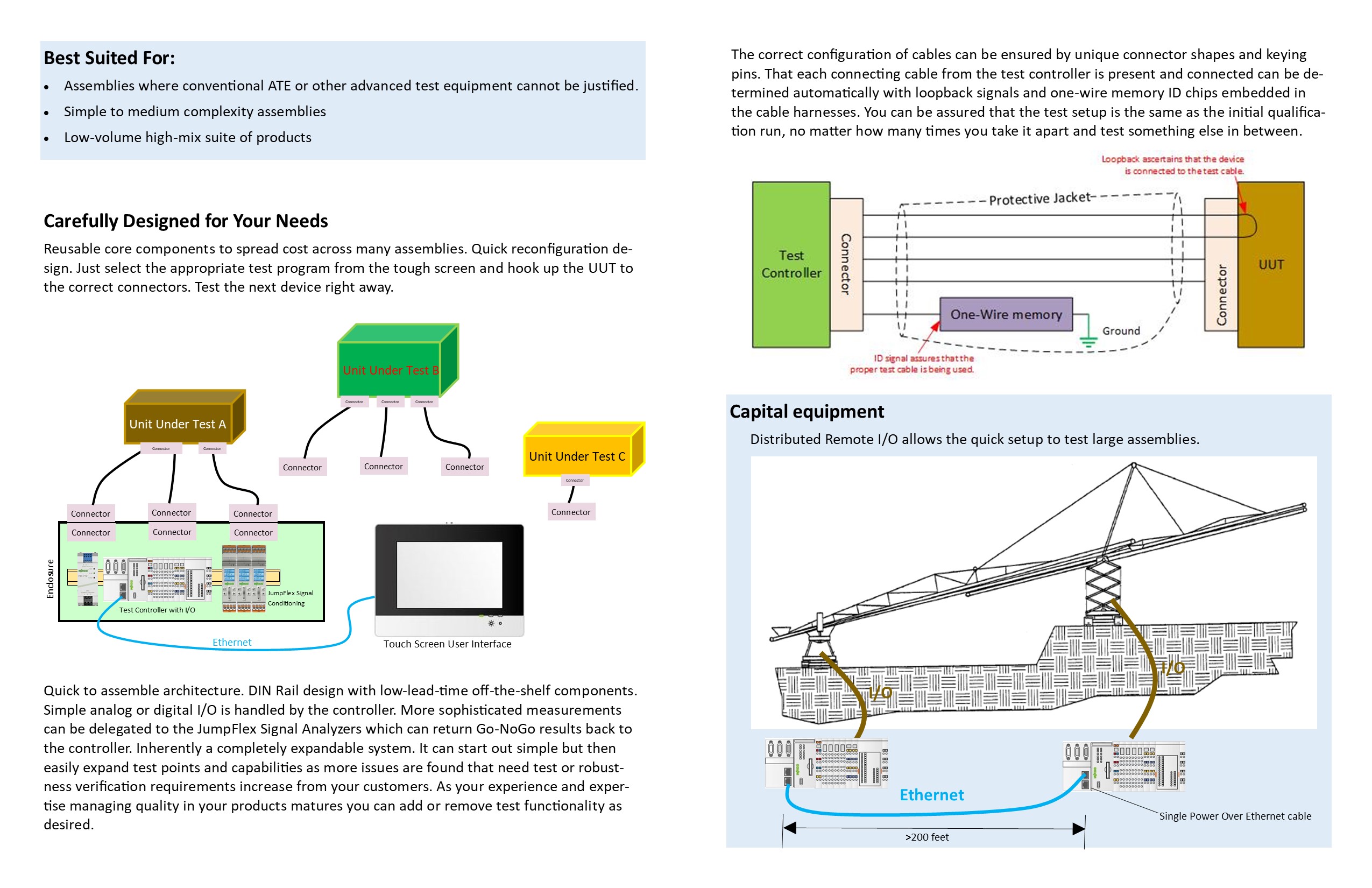
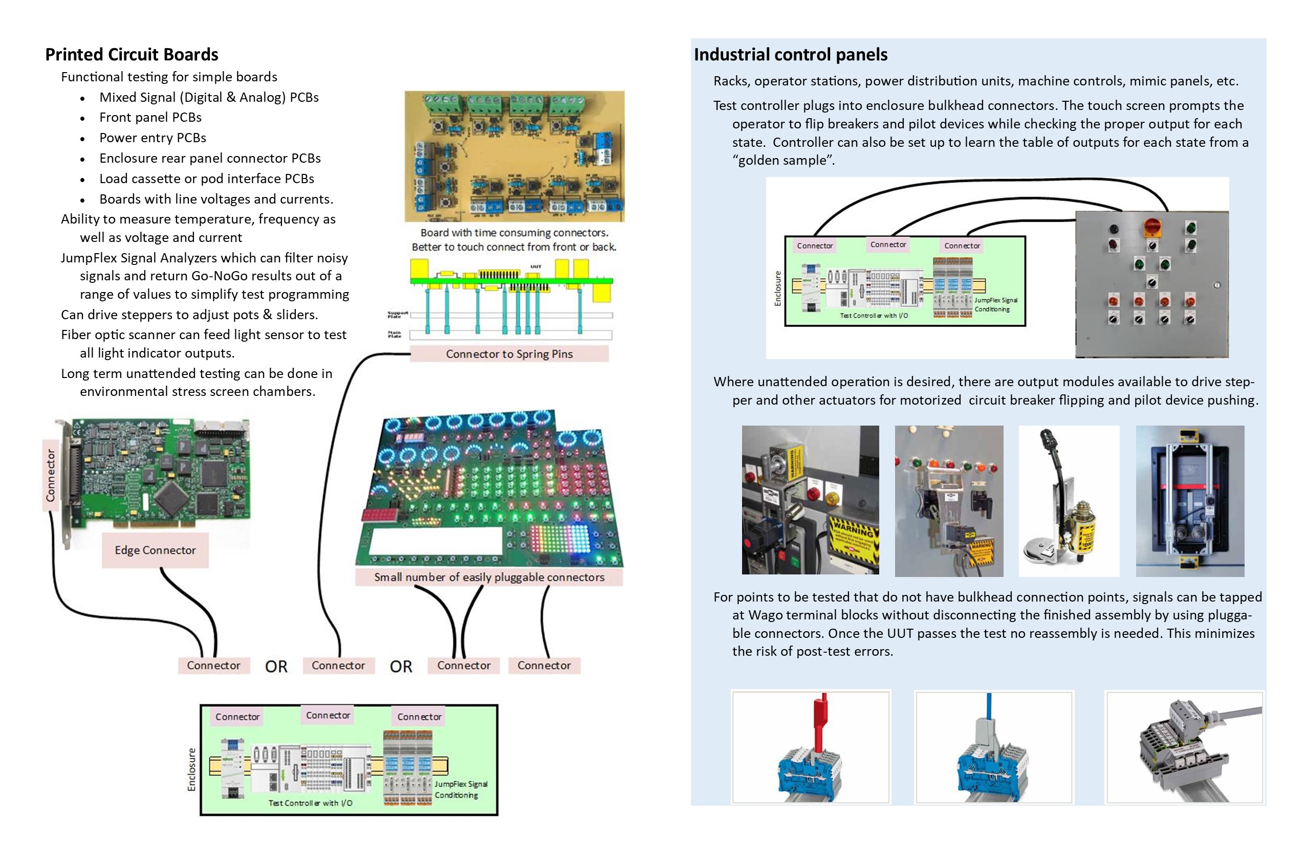
I used my experience creating test fixtures, control panels and cables to accumulate applications where Wago products or their competitors
had been used successfully in the substantial California instrument test market.
Each application was illustrated using MicroSoft Visio. Pictures of Wago products were shown in schematics of the equipment they would be incorporated with.
Using MicroSoft Publisher I created a brochure illustrating these applications in the context of our distributorship targeting this market in
cooperation with Wago. Attention was acquired.

Courting CNC OEMs
Problem: There are a lot of CNC machine shops in California. There are also many CNC OEMs trying to get their share of the market. We got a chance to pitch a CNC OEM from overseas at their Los Angeles office. They had been in the US market for a long time but had not expanded their product line much. There were no robots in their portfolio. We wanted to expand our sales of Schneider Electric and ABB products and we wanted to get their attention to do so.
Solution: I made a Visio diagram of the environment around their CNC machine tool. In the diagram I explicitly showed where ABB robots could fit to grab their attention with our most dramatic product they could resell with their machines. Since our proposal was that we could supply them value added features to enhance their machine tools that they could implement quickly and gain some market share, I also showed various networks, power monitoring, security cameras, conveyor controls and loading dock controls that our product lines could be used for.

A Different Sales Strategy
Problem: Our distributor was facing stiff resistance from larger competitors even though we had several really good technical experts. Everybody was fighting hard for sales of big ticket items from the big controls suppliers. The sales manager was going to try a different approach using tier-two brands that would give him strong technical support. He also had a non-technical sales guy who had a knack of getting in through the back door and finding people with problems. As long as he had technical support to back him up after he got in the door, he could get into places others had ignored. The sales manager needed a quick drawing to explain his plan to his management.
Solution: I quickly found the necessary clip art online and populated a Visio diagram with them. It took a few iterations before we could get the fuzzy gut-feeling idea in the sales manager's head put down into a clear concept. We also analyzed the CRM to find enough specific customers for the tier two lines. The boss liked it and it kind of worked for a while.

Remote I/O
Problem: Customer that operated a number of oil wells in Los Angeles approached us for a proposal to modernize their tank to truck scheduling process. Customer hinted that they were most comfortable with ABB equipment but did not provide many specific details of their existing outside plant. We did know that they wanted to move from a fixed schedule of truck pickup rounds to a schedule based on tank level status.
Solution: To gain their confidence I made a diagram of a potential generic system of tank level reporting based on ABB equipment. What made this application a bit different is that what comes out of the well is not just oil, but also water, an emulsion of oil & water, grit and gas. ABB did have equipment that could handle this "multi-phase" material. They also had a robust suite of cellular and RF products that could cost effectively send the sensor data back to a truck dispatch office. The diagram allowed us to demonstrate that we could understand the specifics of their application and move to the next step of serving their needs.

VFD Application
Problem: Our business is to provide variable frequency drives (VFDs), PLCs and HMIs for food processing and other markets. We needed our own graphic to help get the customers to identify what mixing technology they were using or wanted to use and then show why we needed a specific VFD sizing for optimal energy consumption and motor life.
Solution: I compiled relative machine data from several reputable manufacturers and placed it in an Euler diagram. The diagrams were original created for mathematical logic and set theory, but they can be nicely adapted to show the preferred zones of application of a device using non-numeric attributes. With this diagram we were able to get the information we needed about the application needing VFD controls without showing any preference between mixer OEMs.


Medium Voltage Control Panel
Problem: A contract manufacturer of industrial control panels was trying to satisfy an incomplete bid package from the Port of Long Beach. Our distributor team wanted to demonstrate that they could competitively supply everything that was needed for their bid. The contract manufacturer selected a poorly defined medium voltage splice panel from the bid package as a test case.
Solution:
I used MicroSoft Visio to show the approximate layout of the control panel as well as to
suggest a number of additional components that were not specified in the bid package.
The distributor had a wide variety of products that would be useful in this application.
With this we were able to show that they were needed without any opposition.
Drawings have an authority of their own that verbal suggestions do not have.
The spacing and sizing of the components would have to be determined after the port engineers decided on the actual operating voltage,
and the shop's licensed Professional Engineer (PE) would have had to bless the overall design.
However, for budgetary quotation estimating and to save time using the limited experts the contract manufacturer had on hand,
this detailed diagram allowed the distributor to secure a place at the negotiating table.

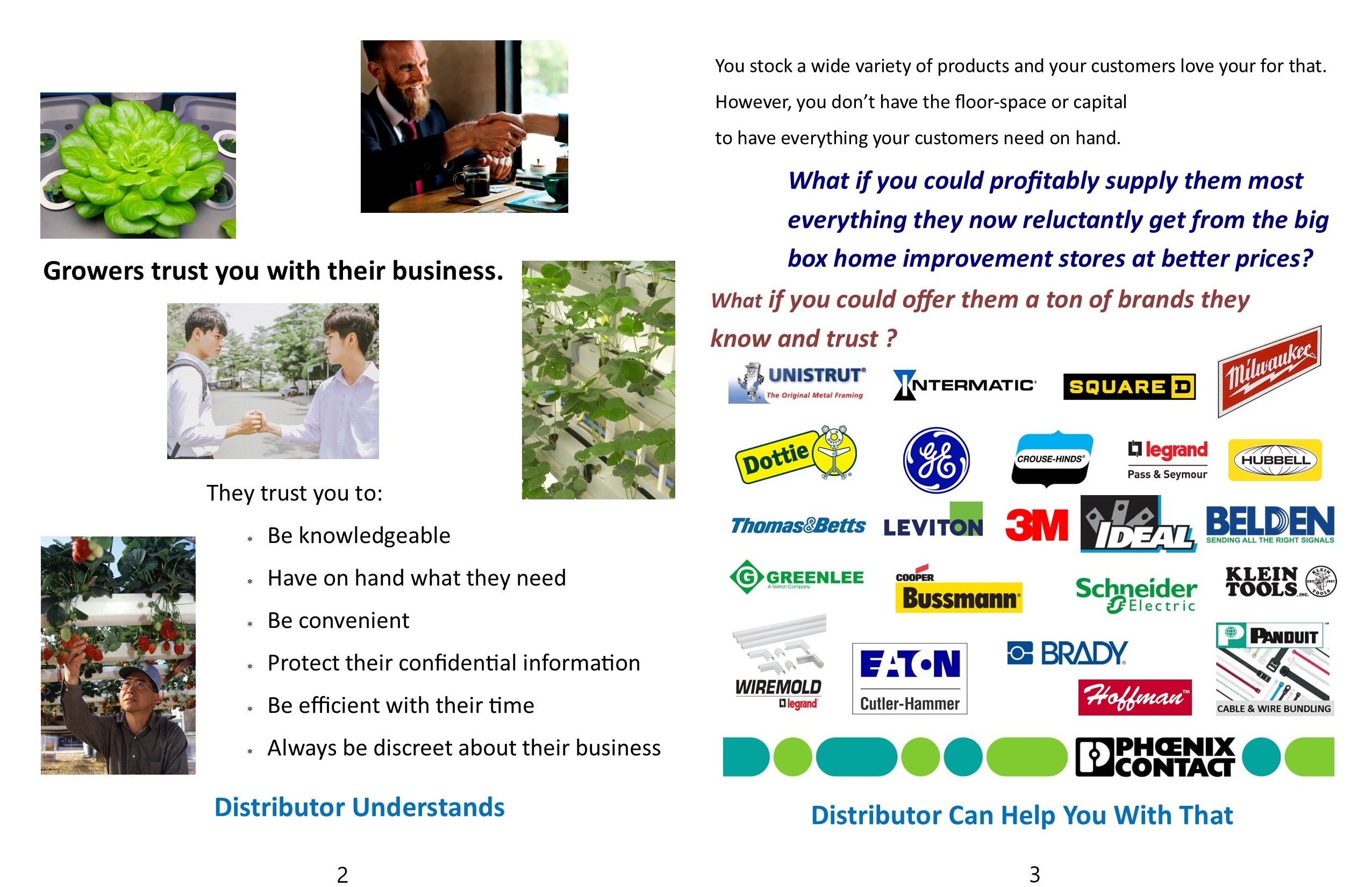
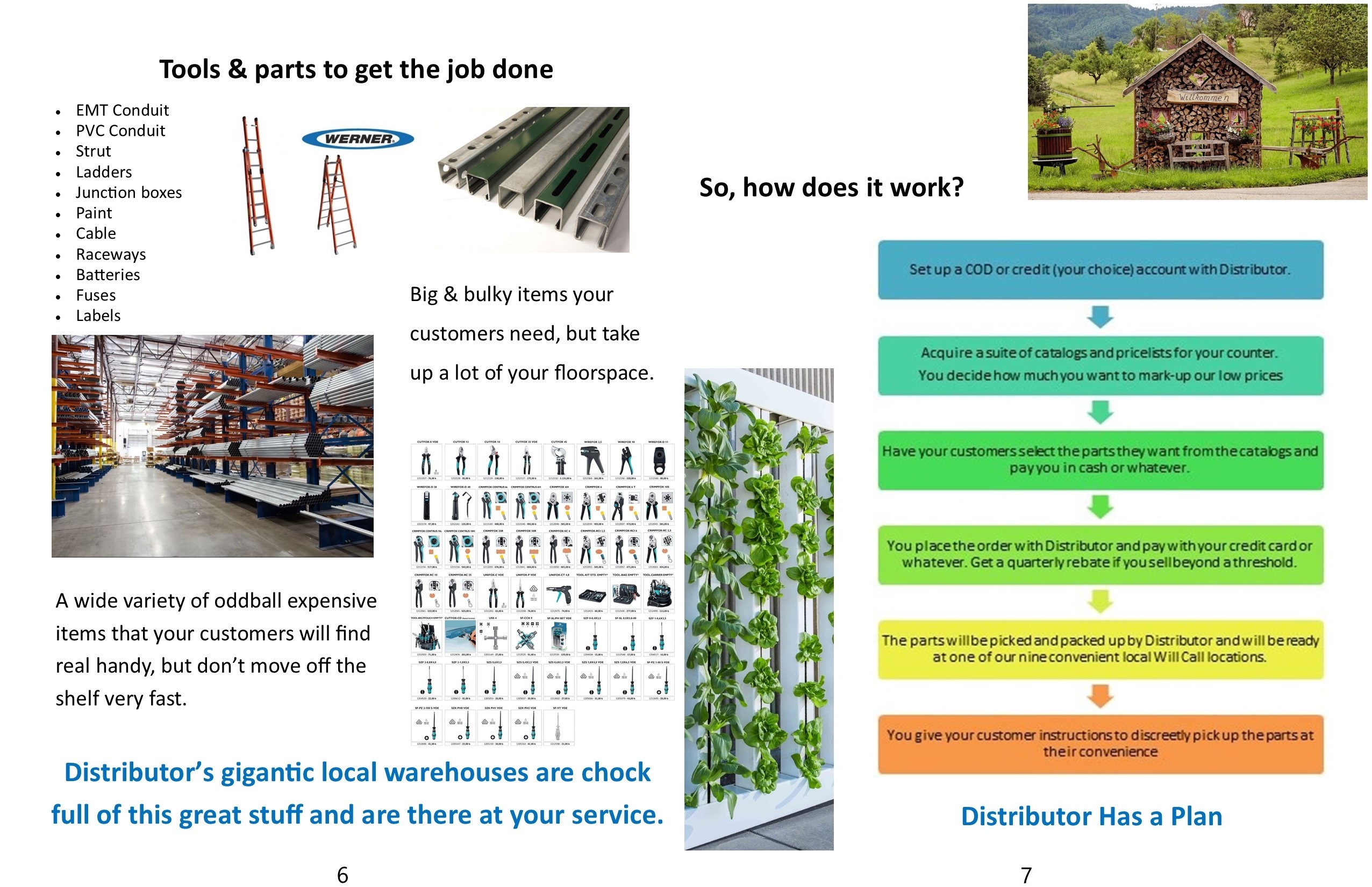
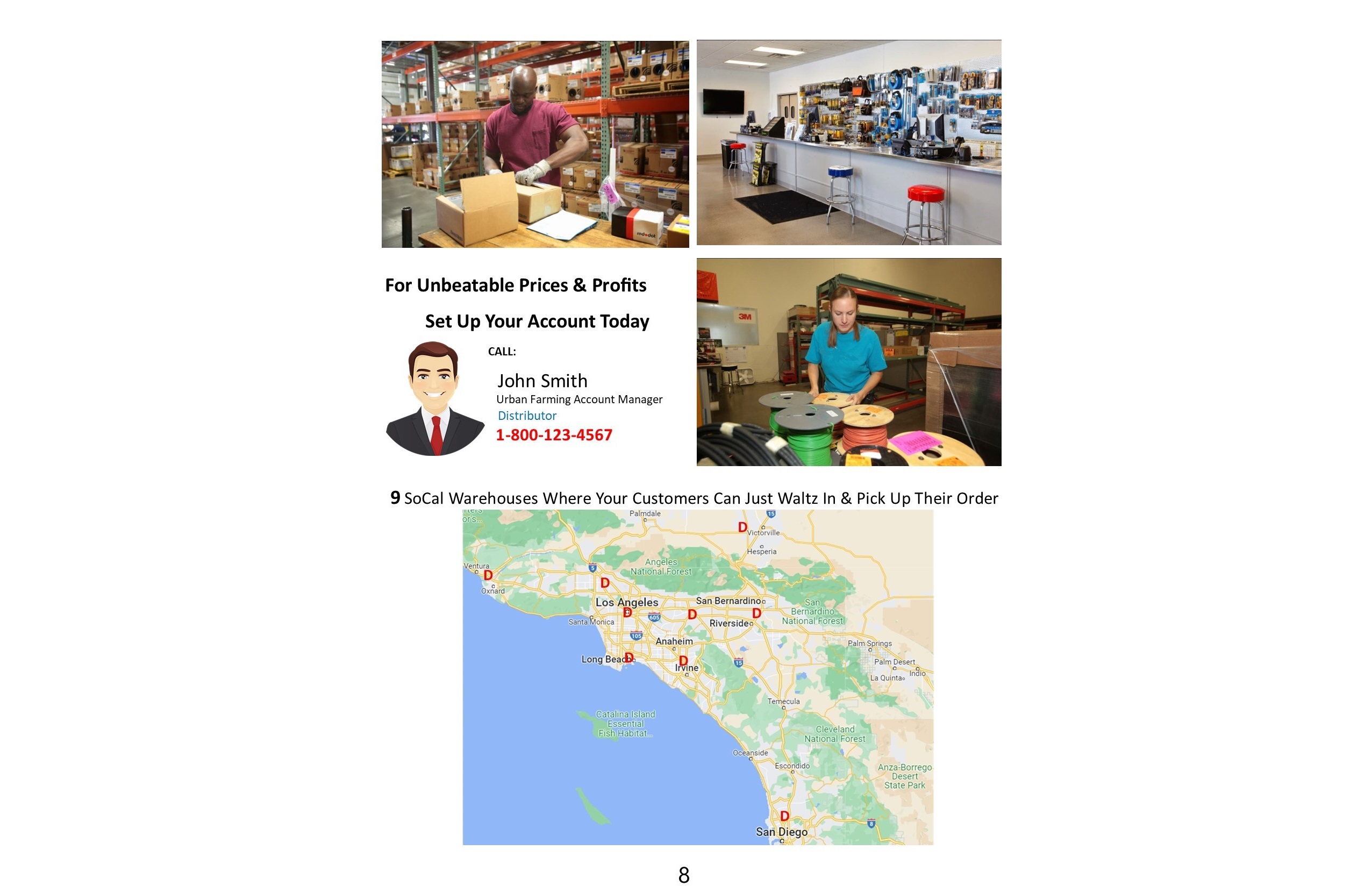
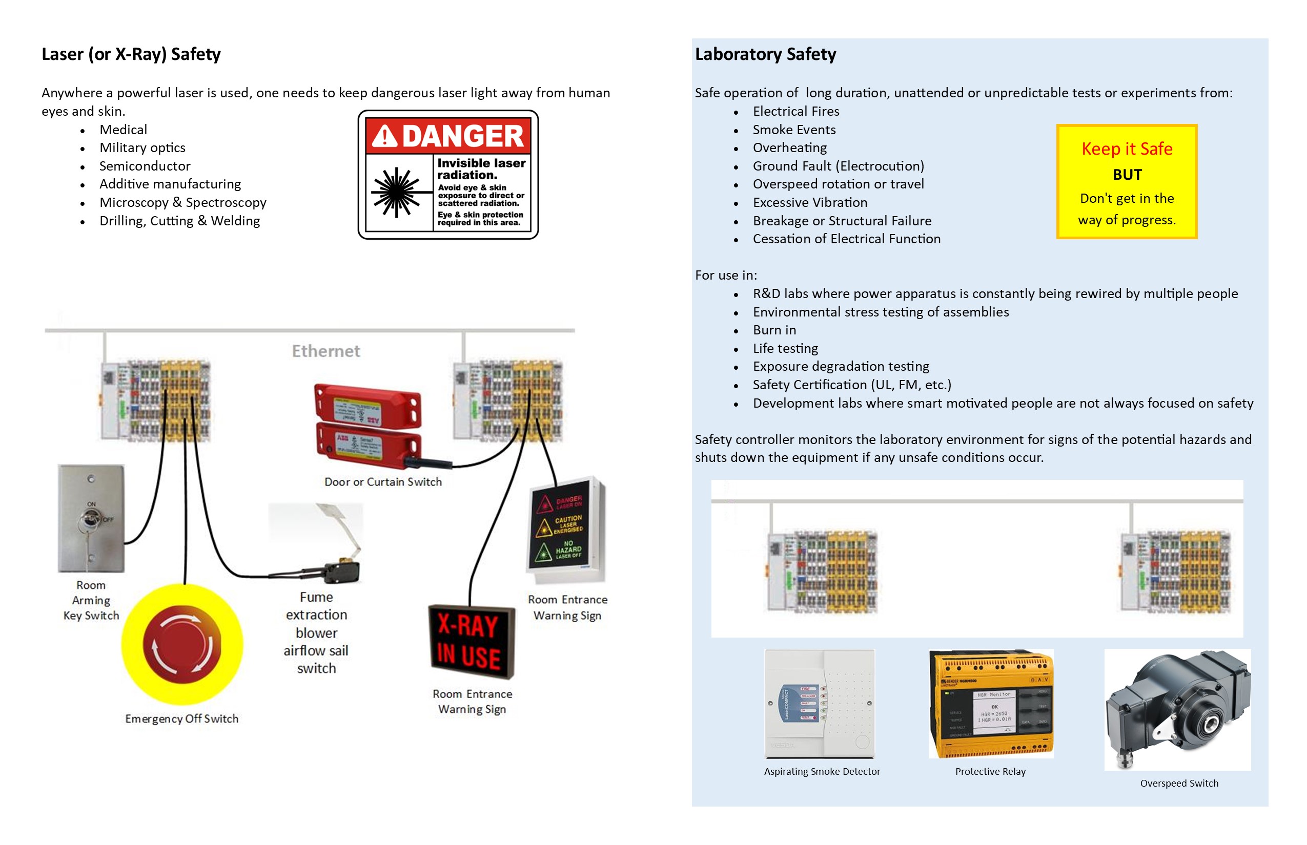
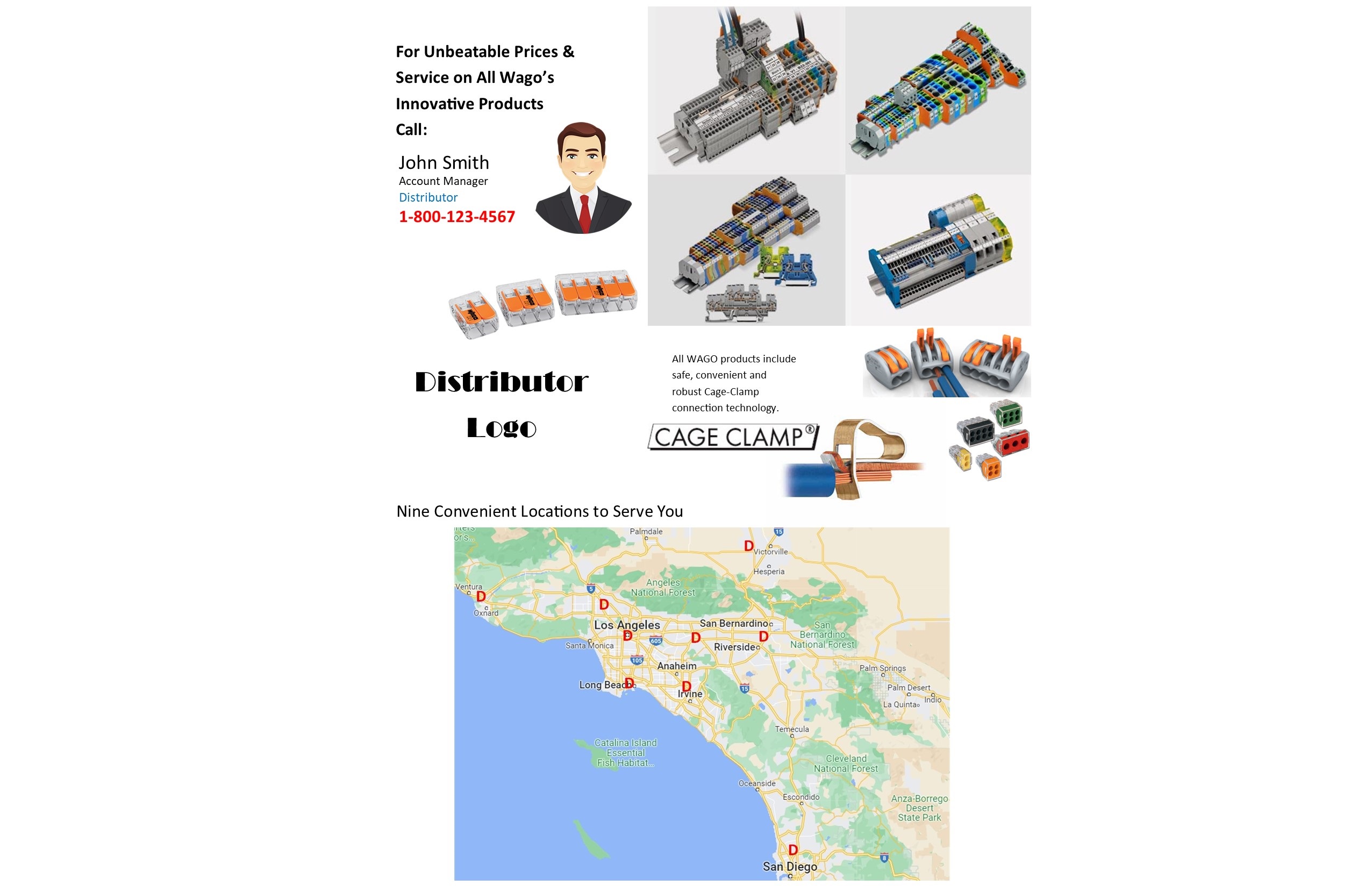
Urban Farming
Problem: The distribution territory we had to work with was poorly developed. Any decent accounts were already issued to more senior salespeople. The typical businesses to go after already had long standing relationships with our competitors. We did not have the time to wait for our competitors to mess up so we could get a chance. We needed business where the other guys were not there. It did not take long in driving around to notice that there were a lot of grow shops and hydroponic businesses. We also learned that a lot of the individual growers shopped at big box home improvement stores for electrical supplies using their credit cards. Our distributor's prices were much better than those of the big box stores and they also accepted COD credit card payment. We needed a way to capture that business.
Solution:
I had a friend whose wayward but lovable son was a former grower and I interviewed him at length about the business.
He was very eager to tell me all about the business, possible with hopes that I could convince his dad to let him go back in that highly risky profession.
I learned enough about how our target customers think in order to craft a pitch to the grow shops to essentially be our subdistributors.
The brochure was created in MicroSoft Publisher. Most of the illustrations were off the distributor's own website, the rest was purchasable stock photos.
The flowchart plan was created in MicroSoft PowerPoint.
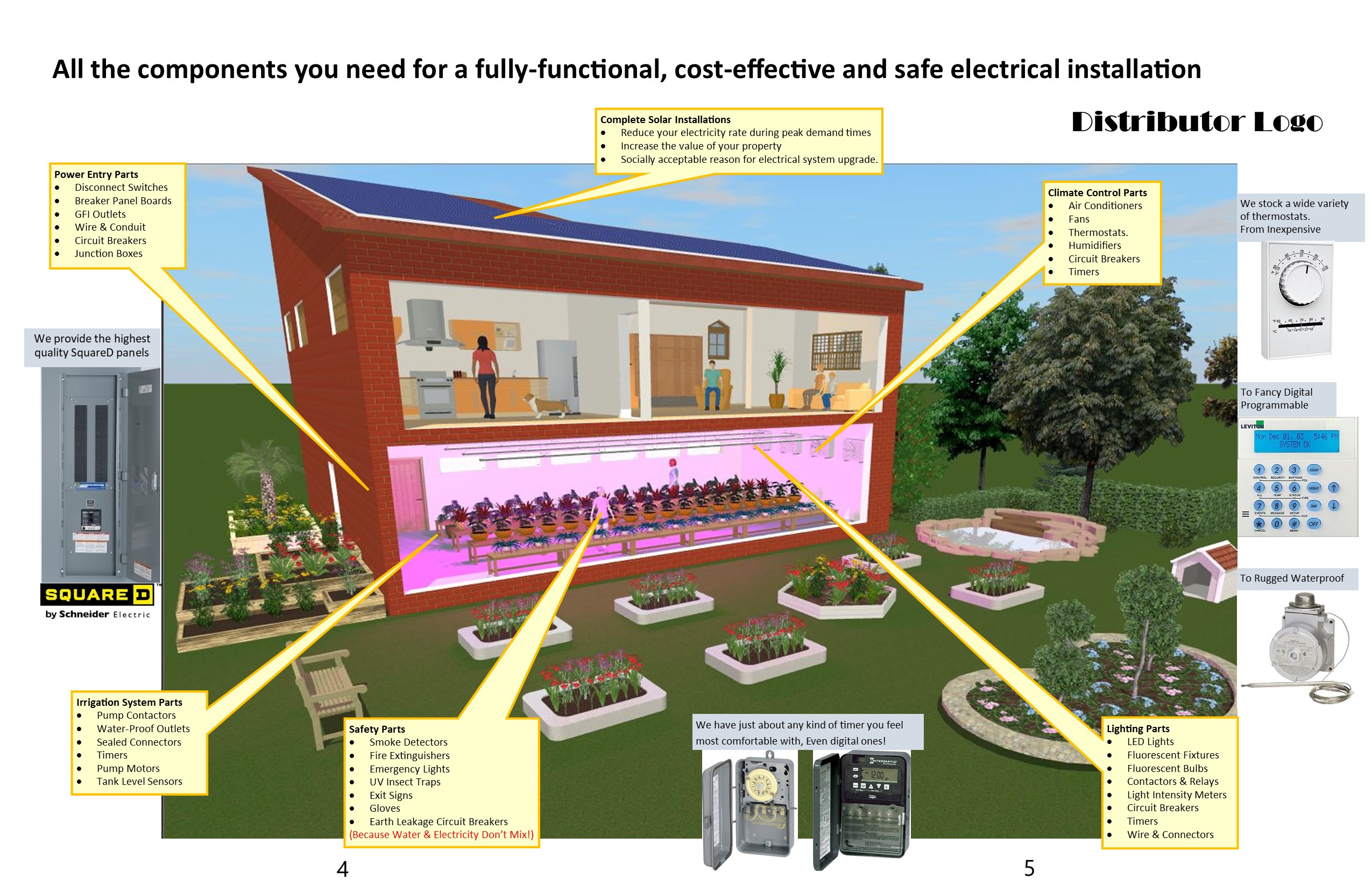
The centerfold was made by taking a screenshot of a 3D model of a home I created using BeLight Software's Live Home 3D.
This very inexpensive program from a Ukrainian company in Odesa allowed me to quickly create a building that had every main element we wanted to sell components for.
Solar energy systems, climate control, power entry, electrical safety, irrigation and lighting all were able to be illustrated easily.
We tested the brochure on several grow shops and they were very interested.
When specifically asked, there was nothing additional that they needed from the program.
We had done our homework well.


VFD Configuration Management
Problem: A water district wanted to manage the configuration of some new VFDs using a PLC. The new drives were to be from Schneider Electric whereas the PLC was already from Rockwell and thus constrained the communications protocol. Since providing water is a very critical operation the district wanted some form of redundancy in the communications architecture.
Solution: I created several Visio diagrams showing what the client had told us as well as what I could find in the online literature from Schneider. They were sent out to the suppliers involved to get feedback and corrections. I went through four iterations until all the questions were answered by the suppliers and the solution proposal was approved by all. Unfortunately, we never got enough feedback from the customer in order to make a full system proposal with a complete Bill of Materials to quote.

Distributorship 101
Problem: As I started to work with a distributor in earnest it became clear that there was much to be learned and also that those "training" me were limited to knowledge only about their own department and function. I was not able to get the full picture of what was going on and where the levers of success were located.
Solution: As I was listening to many people, I entered all that they had told me into a rambling MicroSoft Visio diagram. I used a swim-lane diagram because I was listening to people with different job functions and trying to learn how they interacted with each other. Most of the listening was of laments how some other department or "the system" blocked them from succeeding. Those turned out to be the most useful hints in finding the real way the business operated. However, almost nothing was told in a straightforward manner. I had to strip away the emotional overhead to get to the fundamental steps to a sale. After many refinements and simplifications of the diagram the big picture of an electrical distribution business became clear.
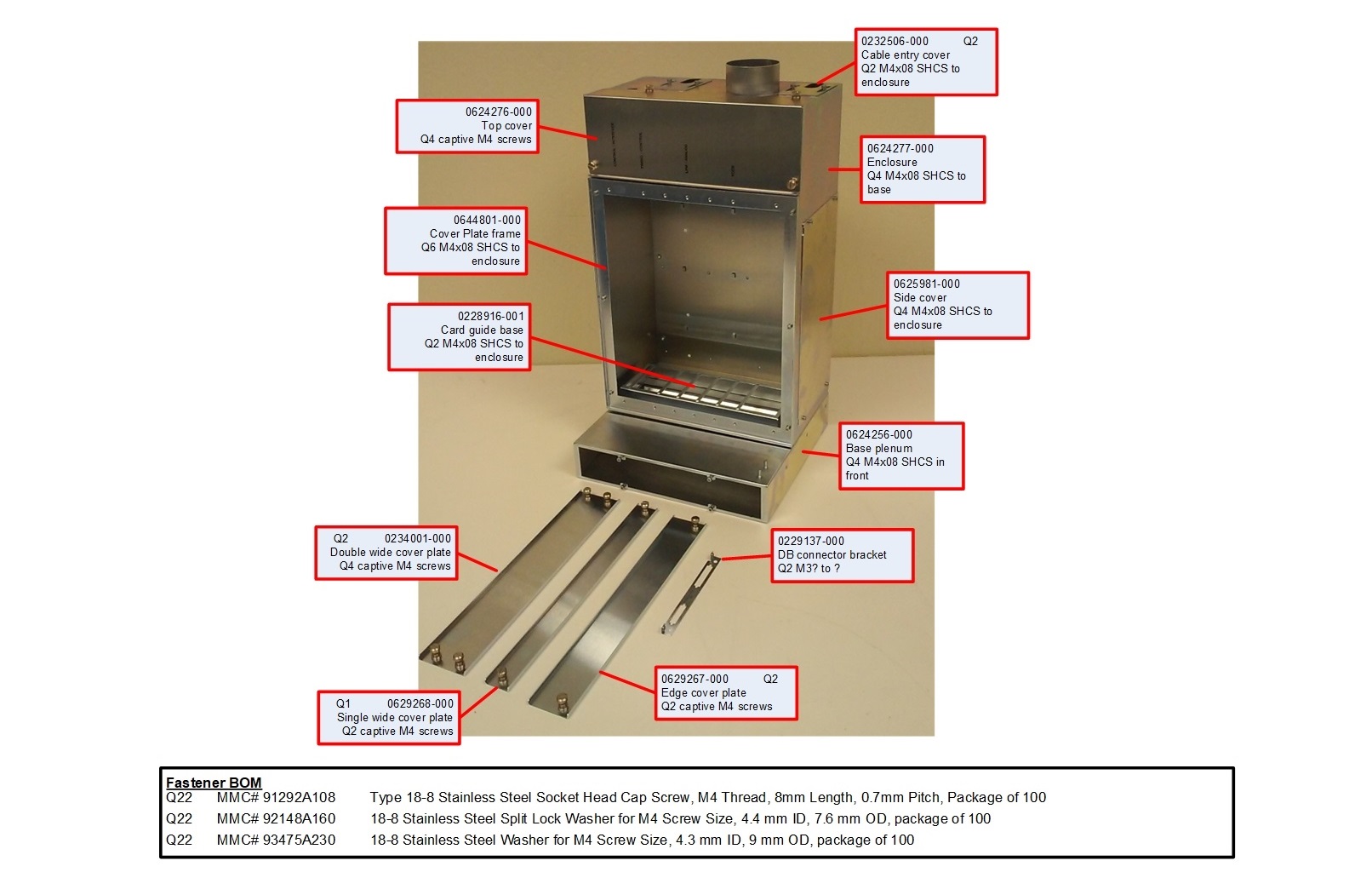

A Pile of Parts
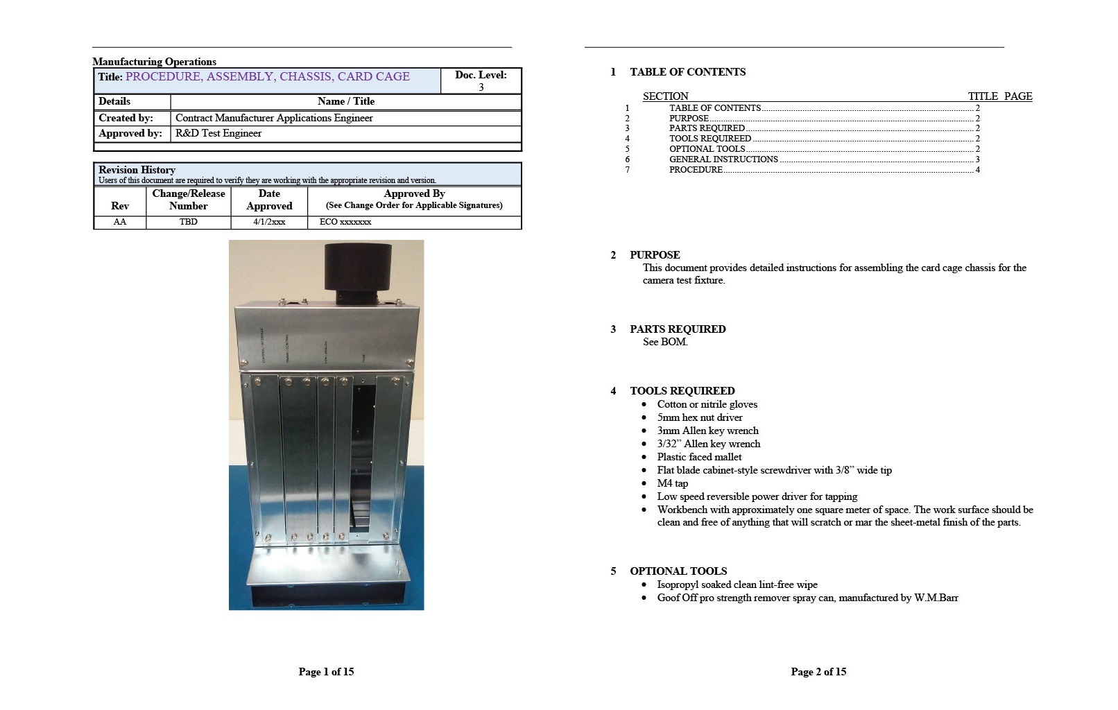
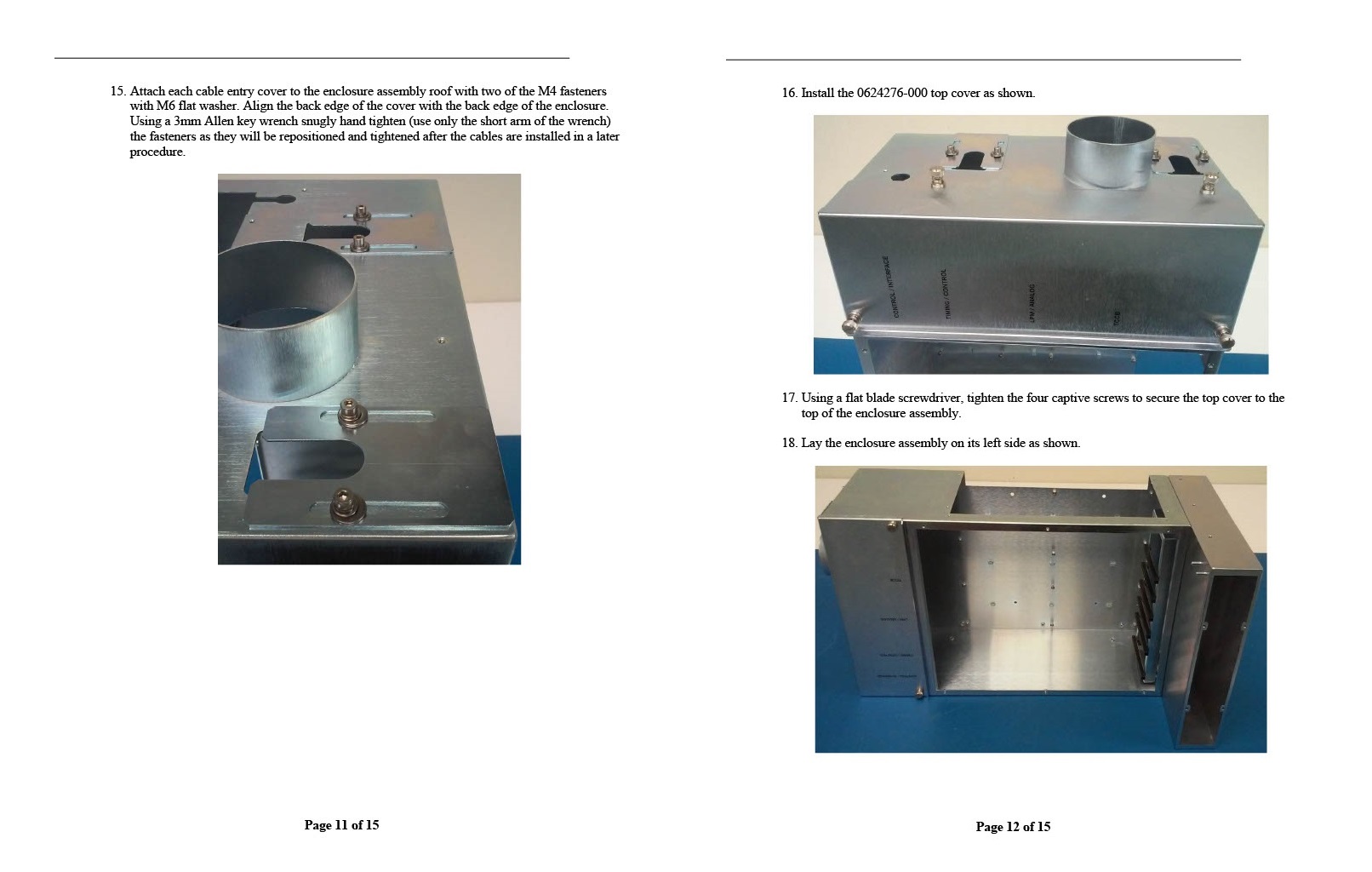
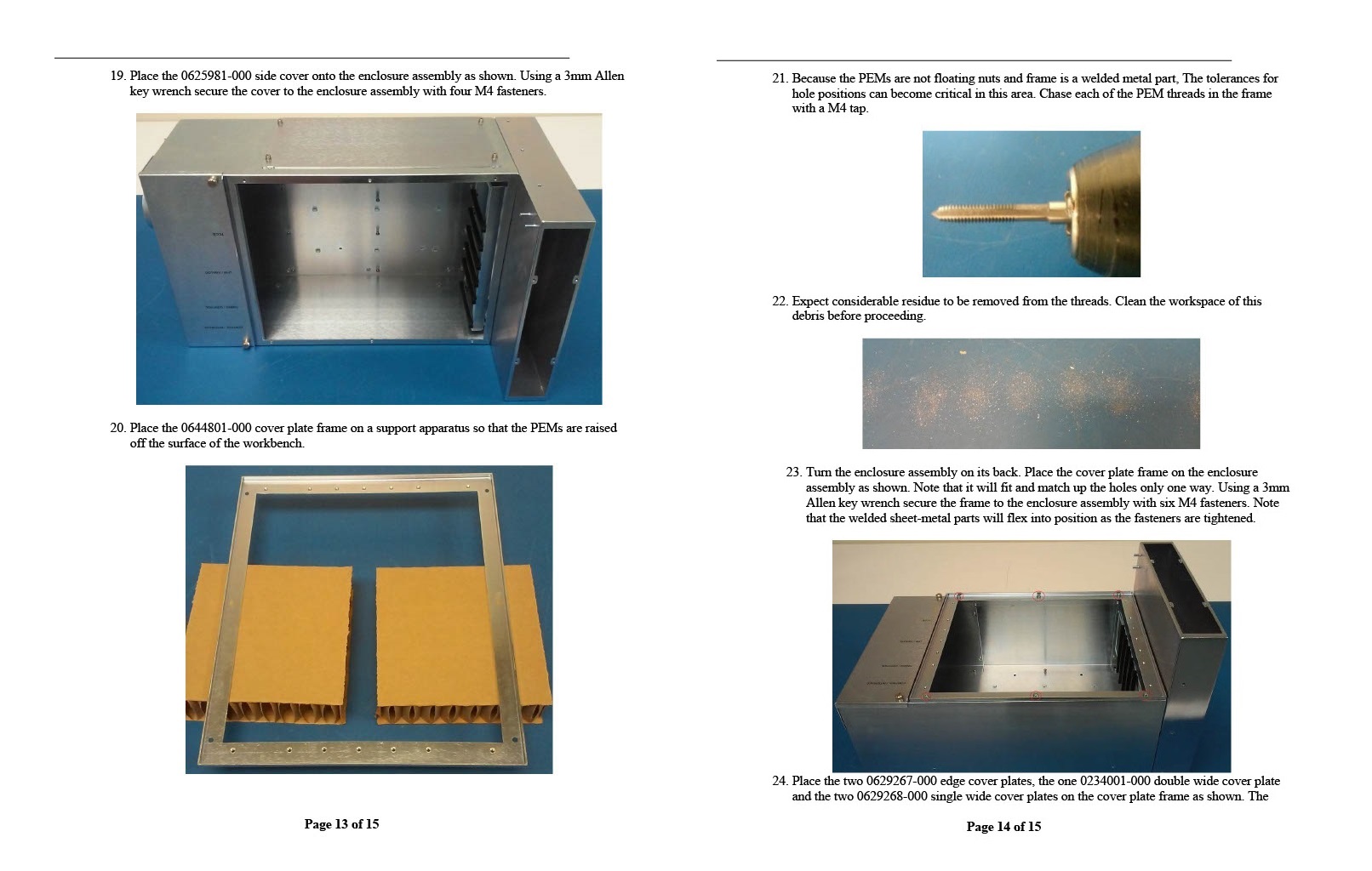
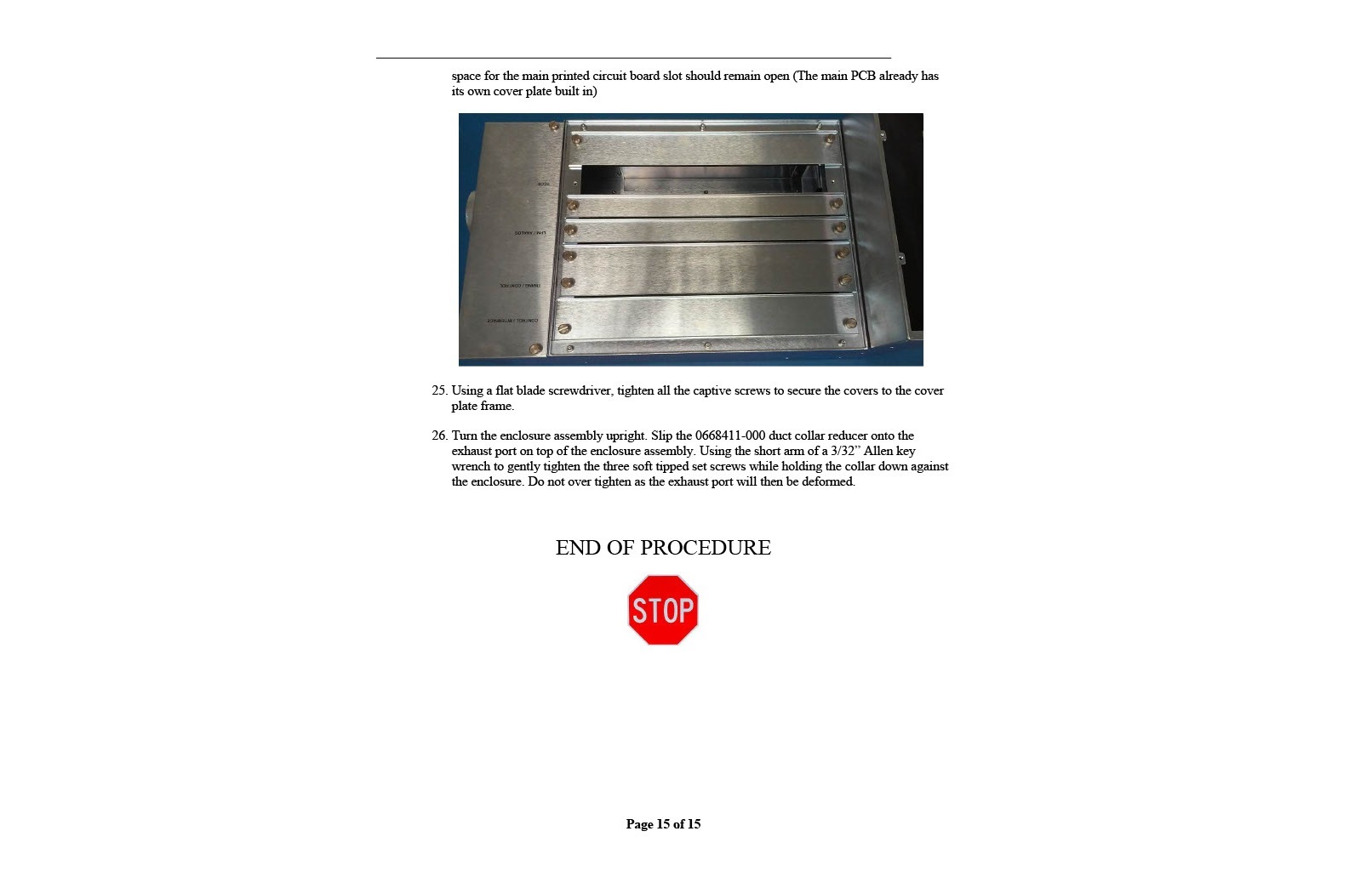
Problem: A customer's R&D department restarted a project that had been on hold for a while. As the preferred contract manufacturer we got a few boxes of parts and was asked to figure out what was needed to to finish the project.
Solution:
Fortunately, all the parts had customer part numbers stamped on them. After fiddling a bit with the parts I
figured out mostly how they went together. I assembled one example unit and posed it neatly with the remaining parts so that
the designers could figure out how they wanted them to be used. On a photo of this semi-exploded view I added all the part
numbers and the quantities that we had received so far. From this quick and simple image our customer was able to get the
necessary changes needed from the various scientists & engineers concerned with the project.
We then pulled the drawings from the PDM, made the metal part drawing
modifications requested, acquired the additional parts needed to make a finished assembly, and assembled the prototype
card cages for delivery to the customer on a quick turn basis.
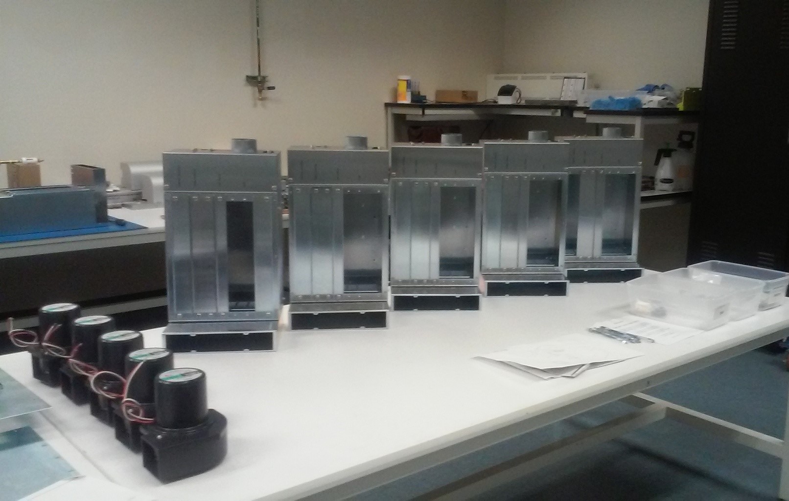
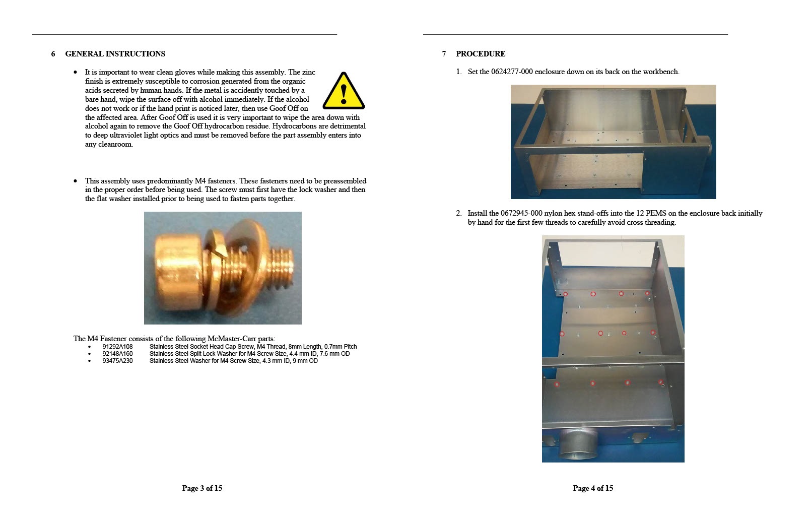
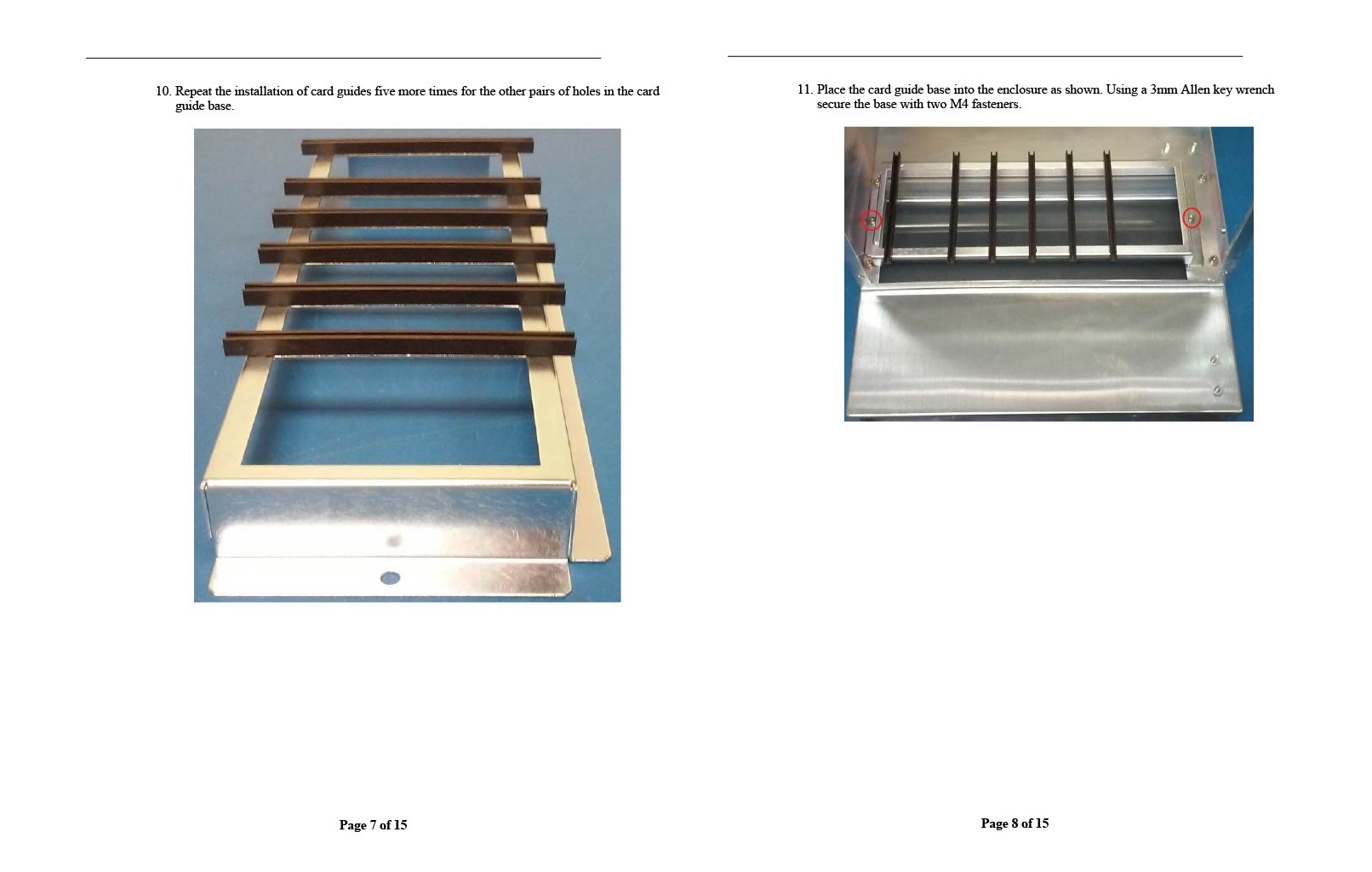
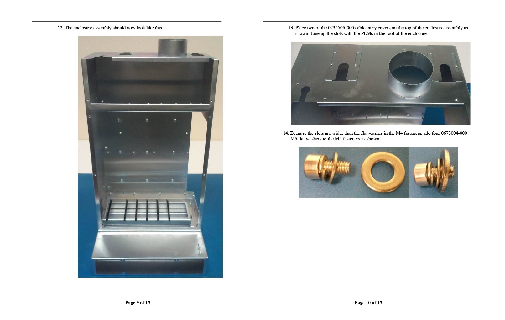
The customer also needed a procedure for assembling the card cage so that any contract manufacturer local or overseas could
assemble it without any issues. R&D eventually had to hand over the responsibility for making these parts to manufacturing
for production systems. That hand-off is often very contentious as manufacturing frequently (and rightfully) complains that the
documentation from R&D is incomplete. My reputation for detail and completeness in these things is why we were the preferred
contract manufacturer for that R&D department.

Information Dense Questions to get Quick Answers
Problem: Our contacts at a customer's R&D department would often send us quick e-mails to get work started as tasks got dumped upon them in meetings. These people were very busy and constantly distracted from one project to the next. Often, they could not remember what they has asked for just a few hours earlier. It was also very hard for them to answer any questions about design details unless they could see the context. The construction of electro-mechanical boxes and cables is all about hundreds of tiny details, any one of which can mess up the project. Our customer needed the prototypes made fast and we needed the answers fast so we could do our part of the work.
Solution:
It is important to be respectful of the customer's time because we are being paid to augment their
efforts as they coordinate them with the other designers in the department. Time to market is everything in the
semiconductor business, so design can be quite chaotic. I read my customer's email carefully, line by line, word by word,
and meticulously constructed a diagram of the environment they are referring to. In this case our customer wanted a box to safely
power up some fans.
From the email, I diagram as much of the box and the associated cables as I can. I look up the details of each part and include
what would be needed to make the decisions. Some parts of the design that are not explicitly specified I can make reasonable effective
guesses about, but I must confirm them with the customer and make sure that the customer really understands what I am asking them to
approve. We are partners with the R&D department. Their success is our success. Other requirements they have quickly sent us are not
able to be guessed and need to be asked in context of what they have told us. That context is often in drawings and devices that already
exist that I can then incorporate in the new design diagram.
Once I have drawn everything I can figure out from the requirements, I add the questions we need them to answer (typically in red) in a way
that they can quickly get context and then quickly provide answers hopefully before they get pulled away to the next meeting or problem in the lab.
Because I made every effort to respectful of my customer's time, they almost always reward me with very quick answers, and if not
than with an apology and effort to get us back on track time-wise. Partnerships take real effort to maintain, but the business (and personal)
rewards are substantial.

Solid Modeling Software Management
Problem: CAD is a great improvement over hand drafting, but it does have some limitations, especially in the design of part families of a general design. There are a number of simple part designs that once topologically defined can be specified with just a few numbers and selection choices. The PTC Creo solid modeling package we were using at the time was able to do that, but the process was not streamlined nor well documented.
Solution: I made this MicroSoft Visio diagram to verify the process that was being told to us by several different PTC support people. Each answer I got was slightly different so I used the diagram to narrow down the differences until I got a consistent response from all sources. By getting an accurate diagram of the scope of the task, my management could then determine how much they were going to invest in the technology. Several PTC products were needed for this application and their license fees are substantial.
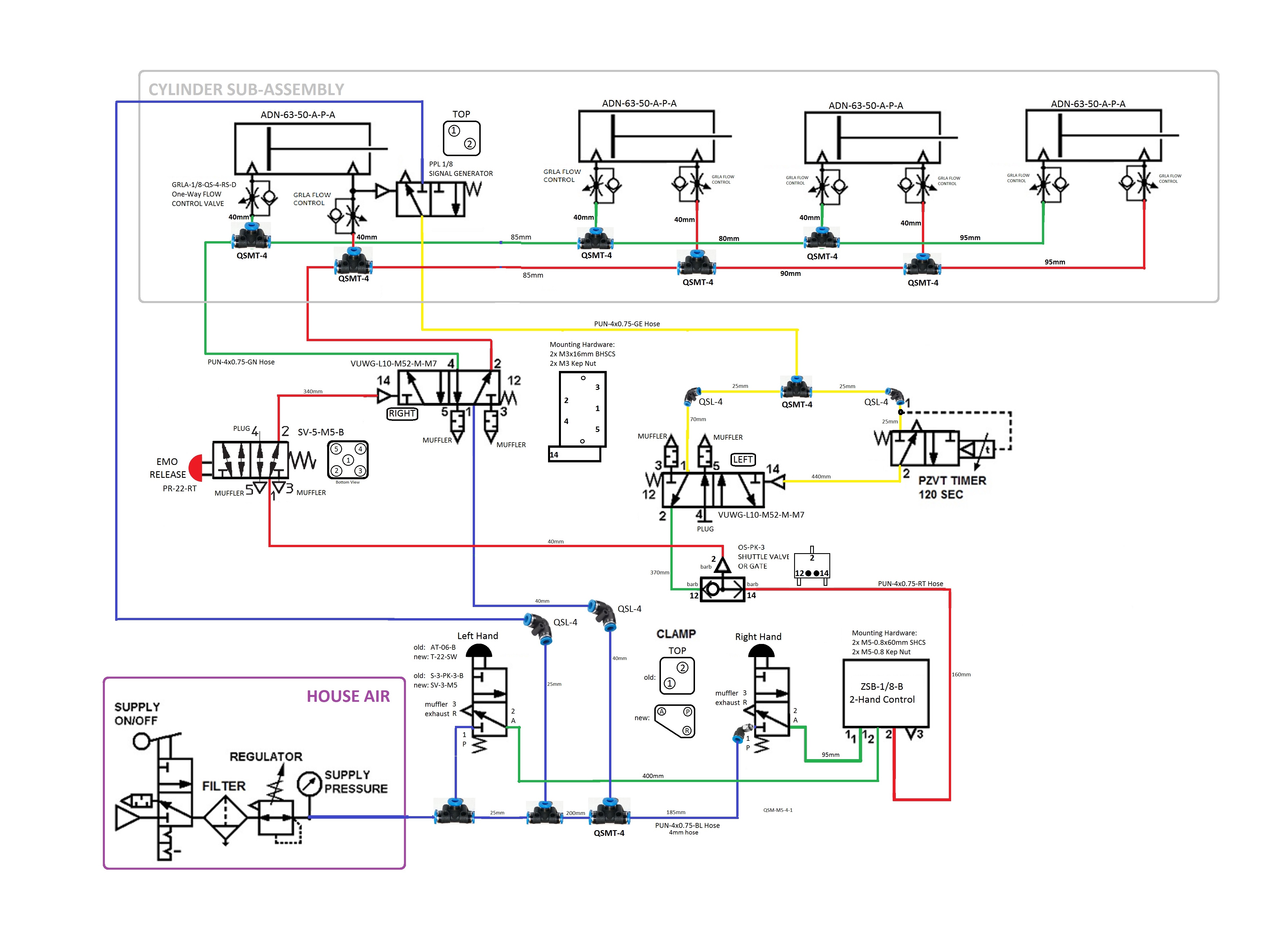
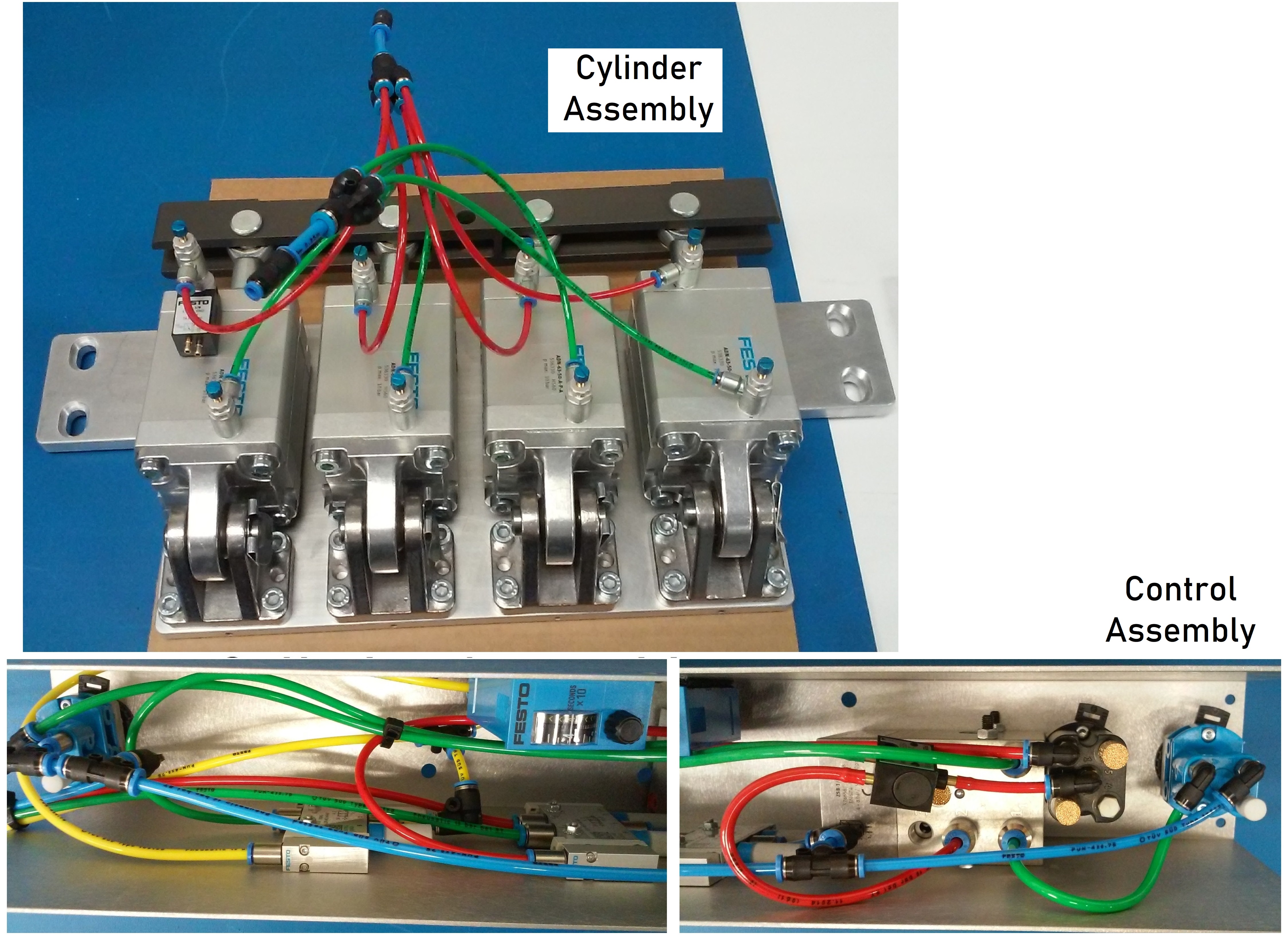
Pneumatic Assembly
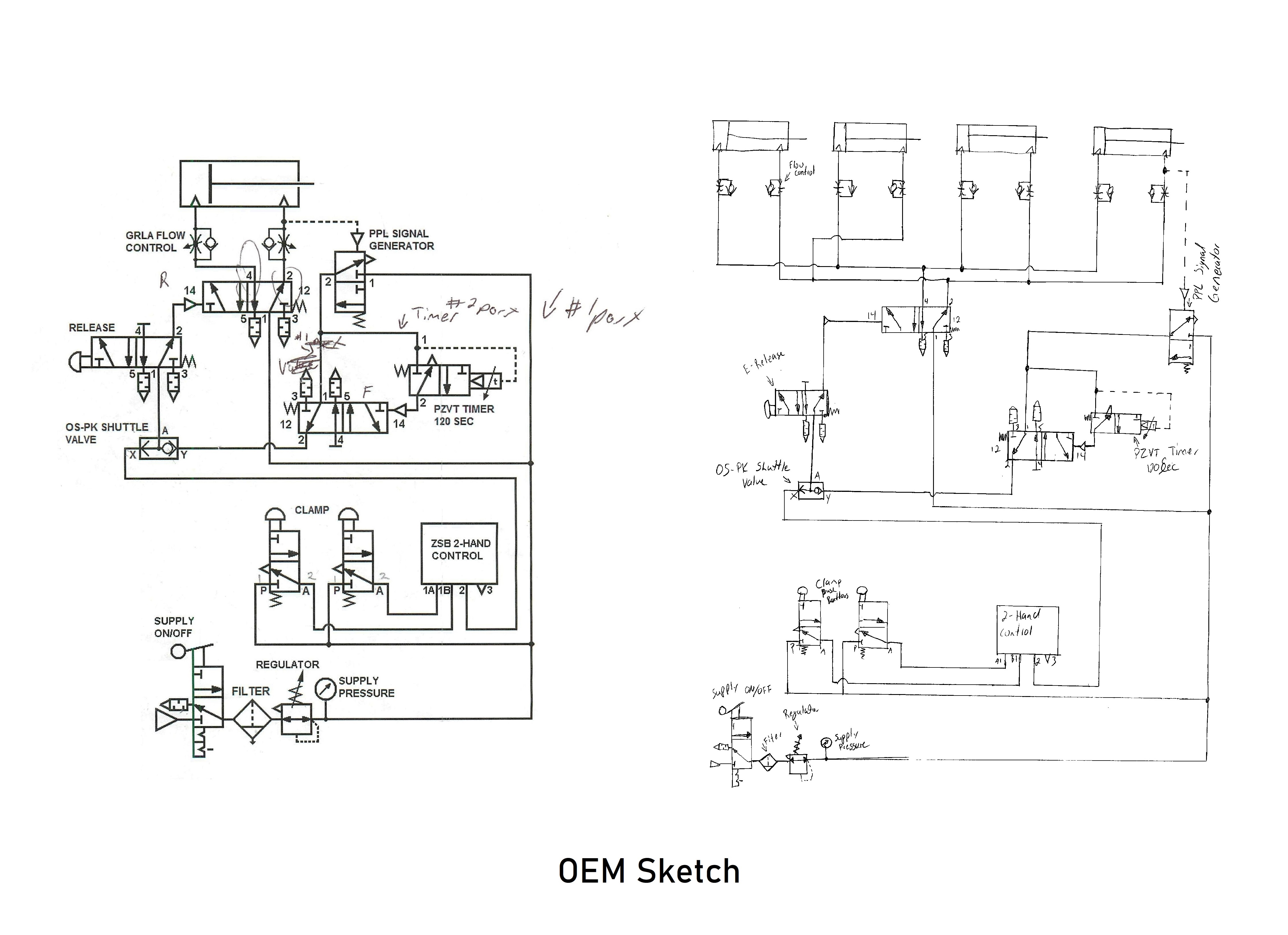
Problem:
Our contract manufacturing business was provided an OEM pneumatic diagram and several units of assembly tooling.
Manufacturing capacity needed to be increased and we needed to replicate the tooling.
Unfortunately, the diagram was insufficient to order the necessary materials or assemble the additional tooling successfully.
An attempt was made to reverse engineer the original tooling, but it was found that there were significant differences between each existing tooling unit,
and the diagram had lots of errors.
Also, the controls were a rats nest of the same blue color tubing in a tight space so maintenance was very difficult.
Manufacturing already had a list of issues with the tooling that they could not address.
The main issue being that it was very difficult to adjust the valves so that all cylinders came together at the same time.
Solution: This diagram was created to account for every part including all the many adapters needed to connect one size component to another of a different size. Hose colors were changed to colors to represent their function to aid in troubleshooting. Uniform hose lengths were determined so that the operation timing remained constant from machine to machine. Hoses were carefully routed so that the circuit could easily be traced, the valves could be seen, and troubleshooting would be much easier. The pneumatic circuit was broken into two sub-assemblies that were physically separate from each other with only three hose connections between them. This diagram allowed replication of the tooling again and again without engineer intervention. Uniform construction created by the diagram's detail reduced maintenance frequency and also made troubleshooting faster and easier.


Quick R&D Box Development
Environment:
Contract manufacturer typically "Build To Print" or "Build To Spec".
This requires the customer to provide drawings that show every detail needed or specifications that cover all circumstances.
For repeated manufacturing with quality and on-time results these documents are inescapable necessities.
However, creating such documentation takes time.
The semiconductor industry is all about time-to-market.
If you spend too much time documentation it slows down the rate of development, then the window of market opportunity is lost.
If you skimp too much on the documentation, then what gets built is either not what is needed or is not robust enough to survive.
Finding the sweet spot is what vexes management to no end.
Problem:
Our contract manufacturing firm was able to negotiate a partnership relationship with an R&D department of a semiconductor equipment OEM.
When I came on board, I started to get requests to build things that had no drawings.
The conversation started by asking how long it would take to create the documentation so that they could order the item that had in their head.
The decision on whether to order from our firm depended only on how much of a time window was available to get what they really wanted versus
settling for a less desirable but faster alternate solution.
They want us to make everything they needed. That was not the problem. The only problem was being able to deliver in the allotted time frame.
The faster we could make the drawings and the items within the available time window, the more of this high margin business we could get from our customer.
Solution:
The first step to solving our mutual problem was to decouple the final documentation to their corporate standards from the actual building of the item.
To order the customer needed a quote from our contract manufacturer.
To quote we needed some kind of document that was reasonable close to what was needed.
In a Build To Print situation that would be a full set of detailed drawings and a Bill Of Materials.
However, in a partnership situation where there is a lot more trust, the drawings do not need to be as complete.
The contract manufacturer adds a contingency amount for potential changes and discoveries and the customer accepts that as the cost for getting the
item much faster.
Included in our quotes was producing the full documentation set for the item.
This was logical because we were the ones designing the item based on some very broad descriptions.
I created drawings just sufficient enough to capture what the R&D engineer/scientist wanted and to quote.
Process:
I used MicroSoft Visio to make a detailed block diagram that included all the electrical wiring.
The customer would tell me what they wanted verbally or by email, sometimes with a small sketch, and then trust me to figure out all the details.
I would then build the first article and take detailed notes as I went along.
The customer usually got the physical item within a week or two after we receive the parts that needed to be ordered.
Part lead time became the limiting factor, not our design & construction schedule.
If the customer needed a few more of the item, I built them as I had the direct experience in doing so.
Sometimes I had a technician help me with some of the more laborious time consuming bits.
As soon as I had built the first article and the customer approved it, I then sent my documentation to our low cost region drafting team.
The final documentation was usually delivered to the customer in a few months, which was quite acceptable to them.
They needed the item fast and as long as the documentation came within a reasonable time afterwards everything was OK.
By decoupling final documentation from the quoting process everything was sped up dramatically.
The customer was very happy and the firm was very happy with the profits we were making.
I was happy because the work was enjoyable and the customer repeatedly acknowledged my value to them.


Quick R&D Cables
Problem: What was done for quick production of electromechanical boxes for R&D was also needed for cables.
Environment:
Cables are conceptually bit simpler than boxes.
But, the details are less forgiving to mistakes as there is less physical room to compensate for dimensional mismatches.
Wires must match the contacts. Contacts must fit into the connector body.
The contacts each connector mates with should be of a different surface material to prevent fretting.
All the wires must be able to fit inside the back-shell while allowing a sufficient service loop for cable flexing.
The wire & cable insulation must be appropriate for the environment they will be passing through as they will have no metal box to protect them.
The details must all be just right to make a safe, robust and usable cable assembly.
Some cables are straight forward, others can have a quite involved design process.
Solution:
I used Microsoft Visio along with snips of connector diagrams from supplier web sites.
One can save a lot of drawing time for the initial quotation drawing by reusing detail diagrams and pictures from the connector OEM.
It is especially important to indicate which side the diagram view is for and often both sides need to be illustrated.
Some of my customers were quite knowledgeable about cable construction and specified a lot of details.
For the quote it was best to capture all that customer input.
Sometimes what was provided was not quite right and we had to correct that and let the customer know why we had changed what they has specified.
I never had any of the R&D customers object to changes when I did my homework and gave them the documentation justifying the change.
Smart customers appreciate when you catch their mistakes and keep quality up.
Attention to the Tiniest of Details
Environment:
Electro-mechanical assemblies are all about getting many details all just right so that everything fits, works and is safe.
Sometimes a design made with the best of concern fails to come together in production for a most obscure reason.
This is why first articles are so important.
Problem:
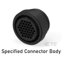
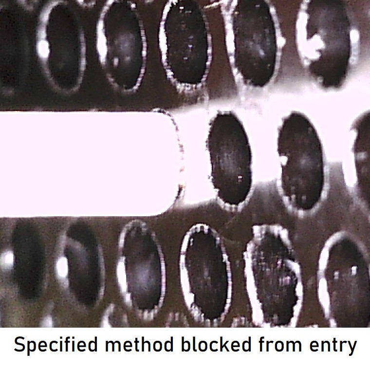
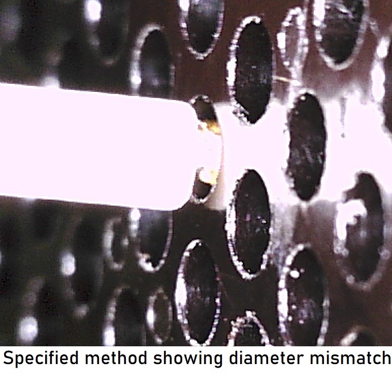
Cable was specified with a plastic circular body using crimp contacts.
The wire gauge was correctly matched to the contact.
However, the insulation was too large a diameter to fit inside the contact cavity.
It is unwise to leave any exposed wire outside the contact cavity as any foreign material could cause a short, or worse an intermittent short or leakage.
A direct short can prevent a cable from working or causing an electrical fire.
An intermittent short can make troubleshooting very difficult even if you open up the cable backshell.
In this case the large diameter wire insulation was needed to handle higher voltages.
A way was needed to get insulation protection all the way to the contact and then convince the nervous customer that the solution would work.
Solution:
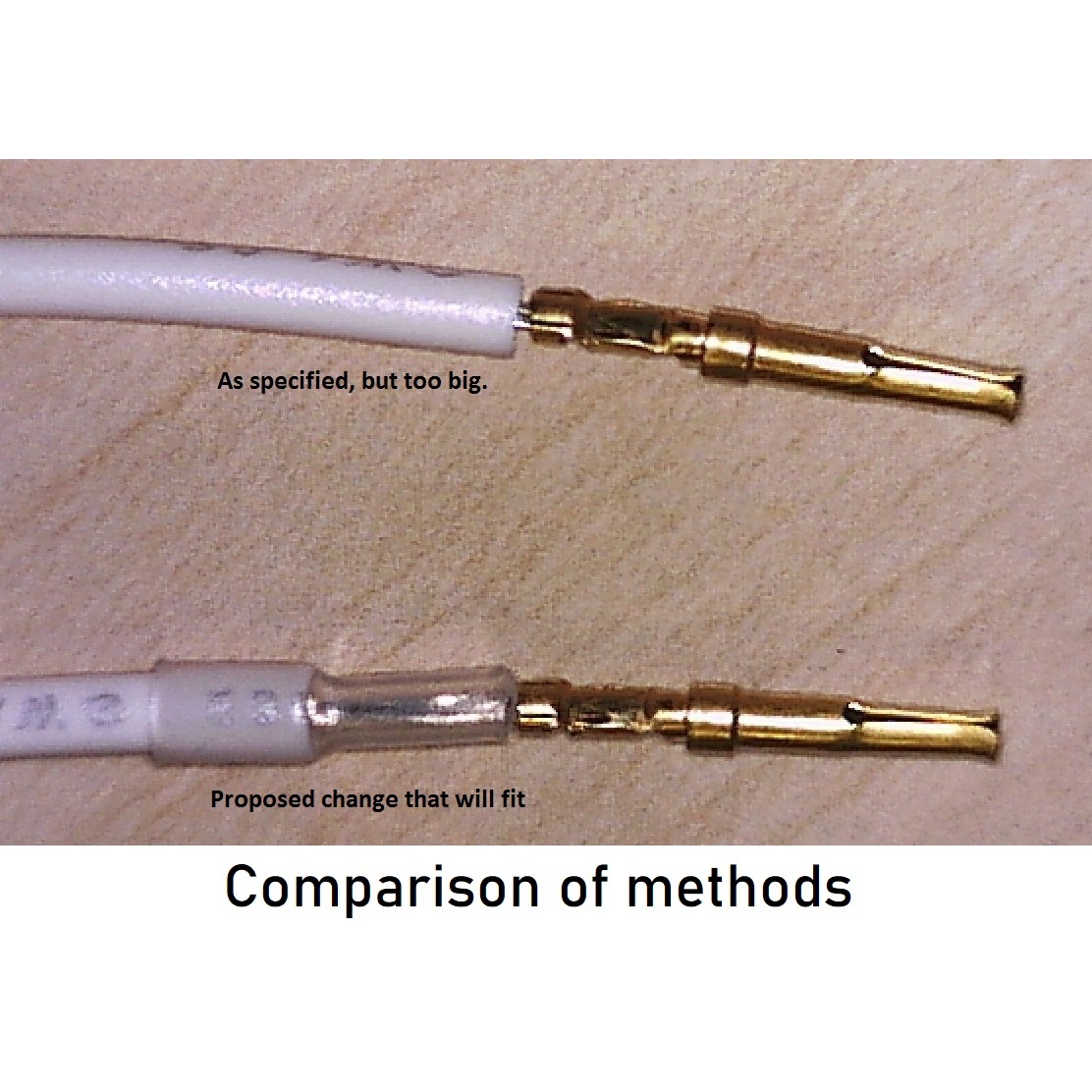
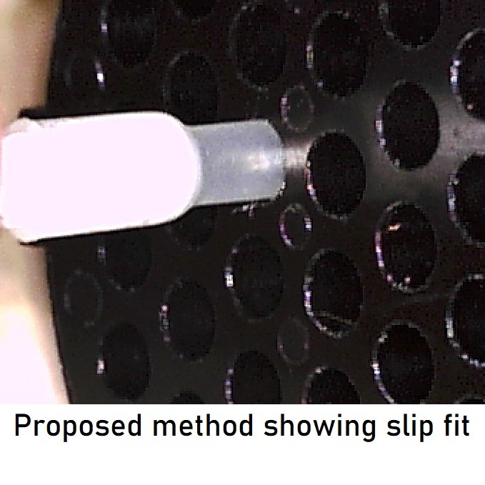
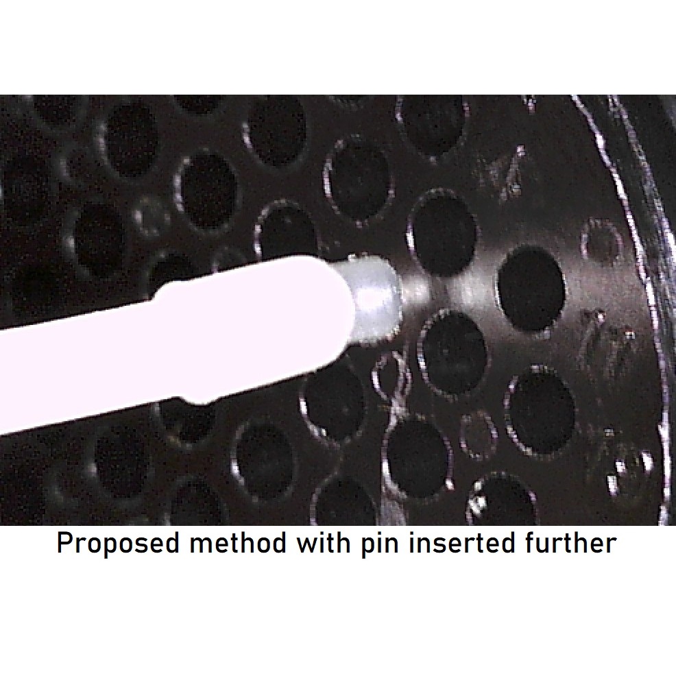
We proposed cutting back the thick insulation to the edge of the connector body and then use
a thinner heat shrink tubing to insulate the rest of the distance.
The connector body was black and shiny which can be rather difficult to photograph.
The contact and the area affected was also very tiny and no normal camera we had could get a reasonable image.
I used a USB digital microscope which is one of my favorite failure analysis tools.
The photographs were annotated and sent to the customer who was very relieved that we had a workable solution and approve the change immediately.
The pictures were also used in the updated documentation for the cable.
The additional purchase order provided for the drafting work more than compensated us for the extra effort needed to solve the customer's problem.
The customer and his manager had yet another reason to feel that we were indispensable partners to their business.


Drawing Clarity Evolution
Problem: Clarity in drawings is always important, but some drawings are more important than others. Our R&D customer had a test fixture power supply design that kept being reused over and over again. New capabilities were being added at frequent intervals. The original drawing from the customer was actually of quite good quality, but it was very complicated to follow. It had a lot of parallel lines which is very difficult for the human eye to follow accurately from end to end without jumping to neighboring line. With all the lines being black it was hard to figure out what was a wire and what was a component. Almost all the available space was packed with lines. There was no more room to add additional circuitry without a lot of rearranging and time spent. We knew that changes and additions were going to happen pretty much forever. Effort to improve the drawing was clearly needed, but it was not immediately obvious how to fix the whole problem.
Solution: I attacked the problem is small increments. I gradually stated to add color. I used color and gray density to differentiate between components and wires. Eventually all wires were correctly colored. As the general design started to pop out from the gradual clarifications it became clear that there some wire busses that if grouped together and kept the same color could be squeezed much closer together because then there would be no need for the eye to actually follow the line to know where it came from. That opened up a lot of space and made the understanding of the diagram much easier. The general rule is that you want to have a much space between parallel wires. But sometimes you can invert that rule if you can remove the meed to follow the lines. Ideally one could represent the bus with one line, but in this case the customer was adverse to that. Still I was able to make it work. Our testing team and the customer also noticed that latest evolution aided troubleshooting greatly. Some drawings need more attention than others.


Communicating With IT
Problem: As I started using more PTC specialized products for electrical design I needed a quiet place where I could focus mostly uninterrupted for long periods of time to fully concentrate. The best place was my home during the early morning. I also had a large monitor and a more comfortable chair. But PTC is rather picky about licenses so I needed IT support to get through our firewall and our rather non-standard network. The IT guy was nice about it, but could not understand what I needed.
Solution: I made a quick Visio of the situation and of what I wanted. I let IT figure it out with PTC and their network equipment. I had done my part. I may have put down more information than what was needed but I did not want them to have to come back to me again and again with questions. That was not going to make them efficient or happy with me.

Proposal Development
Problem: Client wanted to show the general architecture of their proposed fault-tolerant redundant processor telecommunications system. The instructions provided for this project were all verbal. I did not even get a napkin sketch.
Solution:
This is a conceptual block diagram.
It can be used by itself or as the first step in creating more complex diagrams.
The maximize readability, care should be taken to minimize crossed and convoluted paths of the connections.
This drawing went through many iterations until we got to the essence of what the architecture was.
In this case the project never got beyond this diagram. Some projects succeed in getting funded and some do not.
It is highly likely that the lack of funding support was due to lack of detail and annotation of what made this design worth doing.
Just because the diagram simplifies the view of the system does not mean that it cannot have details.
If the client had allowed us to do the next step of creating an interconnect diagram with a budgetary bill of materials,
the credibility of showing actual feasibility, at least at the hardware level, would have most probably kept the project alive.

Illustration for an Email
Problem:
Many functions and components now come in DIN rail mountable packages.
Power supplies is certainly one of them.
However, in helping more of their customers with a greater selection of DIN rail mountable power supplies,
manufacturers have created items that are much bigger and heavier than before.
In a static situation the DIN rail can comfortable hold and support these components.
Unfortunately, many control panels are manufactured far away from the place of their intended use.
After being boxed up in cardboard and foam, they are usually send by common carrier to their destination.
Often, they are send multiple times by common carrier. First from the contract manufacturer to the OEM,
then from the OEM to their distribution center, and finally from the OEM to the end use customer. There
might even be some more shipments in between. All that handling results in frequent shocks to the control
panel and quite often the power supply pops off the rail.
The installer can just pop the power supply back onto the rail, but during shipment a loose heavy power supply
tugging on the wires connected to it and bouncing around inside the enclosure banging into other components can
impart damage that is hard to see and later on troubleshoot. Heavy DIN rail components need to be secured for shipment.
Process:
Most DIN rail component OEMs have special block for the ends or the rails to keep the components secure.
The best not only snap on, but also have one or more screws that tightly secure the block to the rail.
Those end blocks do help secure components to the rail, behave a hard time with the larger heavier items.
Therefore we wondered if there were any larger end blocks or other ingenious solutions to the problem. It
could not be that we were the only ones with this problems. We knew there was nothing in the North American
catalogs. Being that almost all of the DIN rail component OEMS are European, they tend to introduce new
products in Europe first and then bring the more successful ones to America later.
Solution:
I created a quick Visio diagram to show that we were having problems securing DIN rail components with centers
of gravity higher than the support blocks. It was sent of to each of our OEM representatives in an explanatory
e-mail. The results were not satisfactory. Sometimes even with the effort of making a diagram you get nowhere.
The end solution was to use foam blocks between the power supply and the enclosure door. That solution has its
own problems, especially if the foam is not removed prior to power up, but it worked good enough.
Same Space - More Stuff
Environment:
Semiconductor equipment suppliers need to come up with a new tool every year or so.
Consumer electronics now drives the business.
They buy their key components from the semiconductor companies and need something new for their products every November-December holiday season.
To make that next new killer feature (hopefully) semiconductor companies need new equipment at about the same cycle, but just offset by a few years.
The latest technology needed to develop new equipment is being created all the time.
But not all technology ideas actually will work good enough to use.
Equipment OEMs need to test each idea very thoroughly before they proceed to invest the millions of dollars needed to incorporate it into the next generation tool.
R&D labs at these companies need reliable, safe and robust text fixtures to make this happen in the fastest time possible.
It is very frustrating and time consuming to be debugging your test equipment at the same time you are debugging your new idea.
Problem:
Our top R&D customer had a somewhat standard power distribution box design used for a variety of their text fixtures.
This saved a lot of time and money, but after a while new capabilities needed to be added to the box.
It was faster and less expensive to modify the existing design rather that start from scratch every time.
As one adds more capacity to an existing enclosure the existing space inside become more and more tight.
Our customer came to us with yet another power requirement for the already previously augmented and thus stuffed box.
This kind of business was high profit and had little competition if we could deliver what the customer needed quickly.
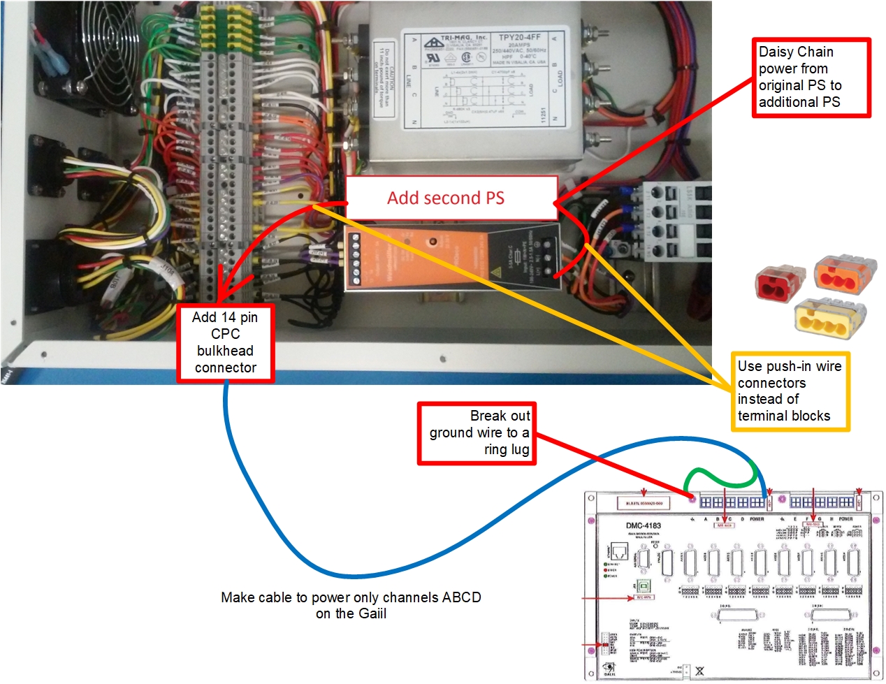
Solution:
The art of these problems is to change as little as possible and still get the job done neatly.
Any change still needed to be robust, safe, neat and well documented.
The expectation was that the box was going to be reused again and that there will be more changes needed.
It is highly likely that we would be doing that change ourselves, so independent of the customer requirements to do so,
it is also in our own best interests to be neat and careful.
By nudging internal components a bit along their DIN rail, one could fit more stuff.
In this case we needed another power supply, and there was still room for the necessary air circulation for cooling.
On the other hand, there was just not enough space for all the extra terminal blocks the customer desired.
To solve that problem I had to refer to my knowledge of construction and propose the high reliability UL listed modern version of "wire nuts".
I made a diagram showing how I would lay out the upgrade using the push-in connectors.
It took a bit of convincing and demonstrating, but the customer came around mainly because the alternatives would have taken way too much time.
The most convincing argument was that the proposed solution was just an internal cable.
It also happened to be very inexpensive. Customers always love a bargain.


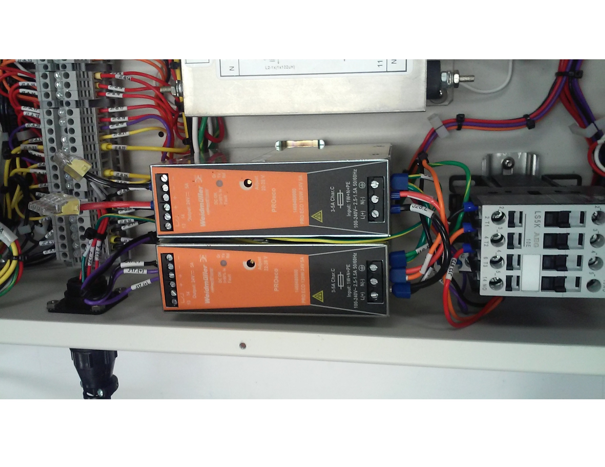
Reuse with Care
Problem:
When time-to-market is the main imperative the logical choice is to reuse whatever you can as long as it can be done in a safe and reliable way.
Our R&D customer needed to power up a new line scan camera in a test fixture.
The desire was to reuse one of the standard power distribution boxes but with new wiring to match the new camera.
Initially this would be no problem as long as the power supplies had the right voltages and enough current output.
The customer had done their homework and all that was OK.
As usual, success comes down to the details.
The output terminals on the power supplies had limited space for multiple connections.
Environment:
Our customer had a lot of rush projects going on at the same time.
So that we could keep track of what was going I gave each project a name based on a flavor as cooking was his hobby.
Keeping track of hundreds of random part numbers was humanly impossible.
The project names kept my customer focused on quickly and accurately answering questions for each project without getting confused.
Solution:
I started by making a prototype of the new wiring so that I could document an exact solution and
have the manufacturing floor produce the rest of the units needed either immediately for some and later on the same way for others.
The lugs on several power supply terminals would need to be stacked.
The customer did not want spacers between the lugs as that would add resistance to the output and affect the voltage on a sensitive apparatus.
Additionally, the customer was worried that bending the lugs would lead to reliability issues. They wanted the lugs to remain flat.
The remaining alternative was to rotate the lugs in such a manner so that none of the wire crimps were over any others.
Fortunately, there was enough space to do that for the number of lugs we had to put on each power supply terminal.
Just enough extra loop length of wire was used for strain relief, but not so much as to cause binding as the sled was inserted in and our of its enclosure.
Once that was made, I created a diagram and pictures to specify exact construction by our manufacturing technicians.
If we were going to make more than a few at a time, I would have measured and specified the wire lengths so that the cables could have been premade by
our lower cost cable team. The customer was happy to just get it made the same day.
For a little extra effort and care we got yet another high-profit purchase order.


Test Rack Interconnection
Problem: Client wanted a rack of instrumentation to test an automotive subsystem. They knew what specific test equipment was to be used, but left it up to us to figure out how to assemble the rack and get all the cables that came with each piece of equipment connected together. Any additional cables were to be identified, designed and built by our cable department. As always, the customer was in a hurry.
Solution:
I took pictures of both the front and back of each piece of test equipment.
In MicroSoft Visio I created a pictorial interconnect diagram using the pictures.
In Visio I can create connection points on any picture or symbol.
This allow me to anchor interconnection lines at specific points, so where the cable will be plugged in is then clear.
All the cables that came with the equipment or that I otherwise knew about were drawn from the various connection points I had established.
Visio also has a useful menu where it helps you easily draw rack configurations in numbers of U using the equipment face picture as each panel in the rack.
With that I was able to quickly show what the front and back of the rack could look like without having to use CAD resources.
We used the completed diagrams as both a confirmation device to get design approval from the customer as well as
a manufacturing instruction for the shop floor to construct the rack and cables from.
Later on CAD drawings were made to corporate standards, but that effort did not delay the production of the rack in time for the customer's needs.
This kind of diagram is the next step in detail and specificity beyond block diagrams & flowsheets.
This diagram focuses on showing what is connected to what and where the connections are made.
It goes beyond a general concept and shows viability and credibility to the solution being presented.
Failure Analysis for 8D
Problem: A line conditioner based on a large transformer that was dampening harmonics and spikes to power a precision inspection instrument caught fire in a semiconductor fab. Dry transformers when they fail usually pour out a high volume of smoke before the insulation material ignites into flames. Smoke in a cleanroom is especially bad. Besides the obvious hazard to the people working there, the smoke can easily damage all the wafers it comes in contact with. Even a small smoke event can cause millions of dollars in damage. The fab owner was very concerned and wanted to know what happened and how to prevent it from happening again.
Process:
The failed line conditioner was taken apart and it was determined the the transformer itself was the cause of the fire.
From the charring on the windings we could tell the approximate area where the fault occurred. We sliced open the transformer coils around the failure zone
and was able to determine the precise winding tap that was insufficiently brazed to make a proper electrical joint.
What remained was to explain to the fab owner where the problem at the transformer manufacturer was and put it context.
Solution:
The manufacture of large transformers has many intricate steps. The process used included many inspection and test steps.
To effectively and believable show this in a concise manner we used a Flow Process Chart.
It is different from a flowsheet as the symbol for each step only describes the its function: Production - Inspection - Movement - Storage.
It was originally used for time-motion studies, but it is also very effective in just showing a complex process in a small presentation space.
This diagram was one of the key slides used in the in 8D presentation given to successfully address the fab owner's concerns.

Industrial IoT Standard
Problem: Our business as a LonWorks Independent Developer was slowing down and we needed to get associated with the next generation of fieldbus technology. I got connected with an IEEE standards working group that was developing way for self-identification of sensors and actuators in systems where there were many of them and sorting out each sensor to DAQ channel was eating up a lot of time. Testing of aircraft with hundreds of load cells and tri-axial accelerometers was a frequently mentioned example. The group had lots of great ideas but had a hard time communicating them to the outside world.
Solution: I landed up being the secretary and editor for the working group. Much time was spent simplifying the design and making clarifying text and illustrations. The most complex of which was the address map for the electronic data sheet in each transducer. Supplementary and matching to the map was the definition of each data field in the map as well as provisioning the definitions for internationalization of the standard by allowing different languages to be used in the data fields. The IEEE refused to have color in their standards so a gray-scale version was made and we used the color version in magazine articles and white papers.
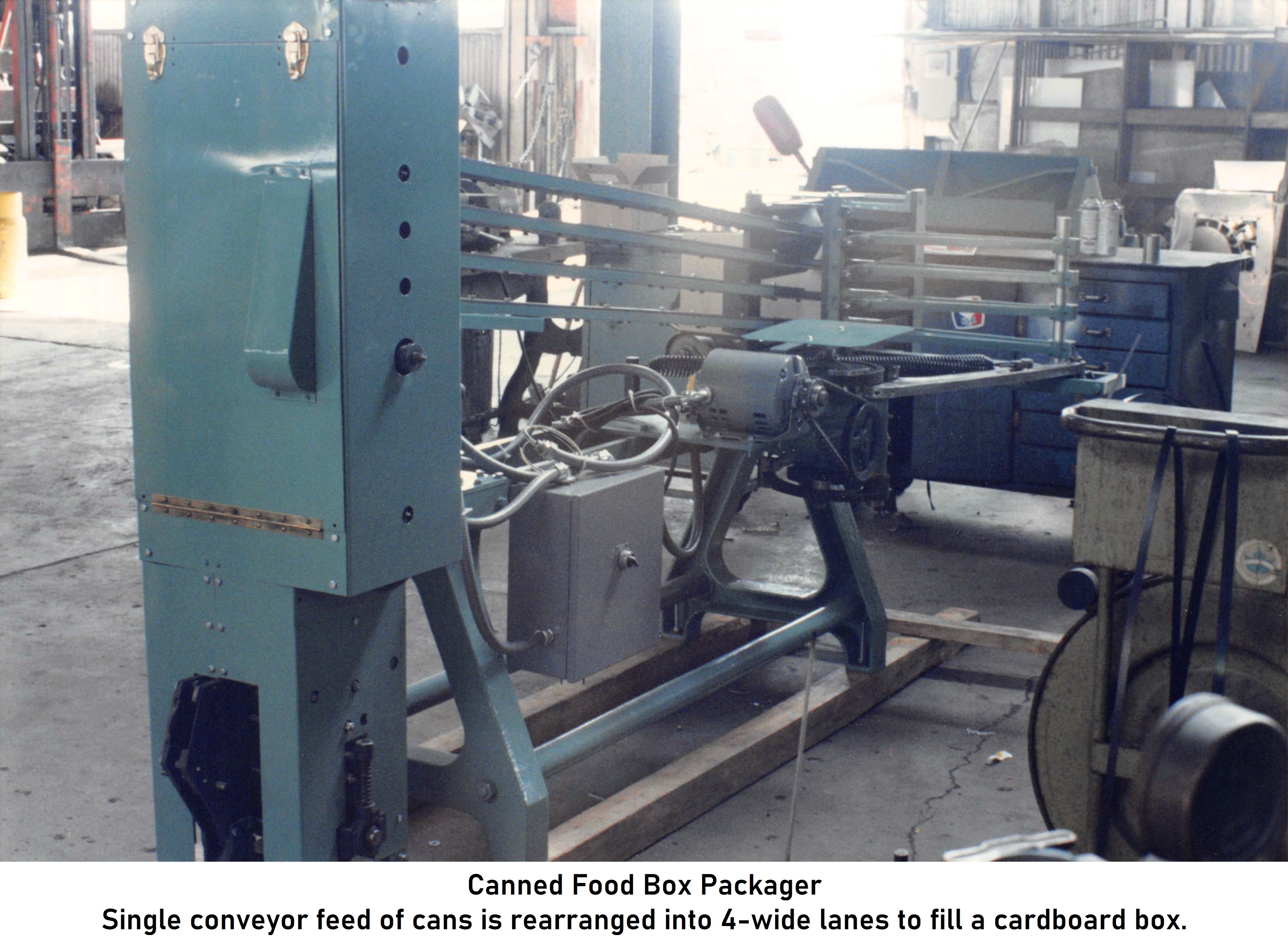
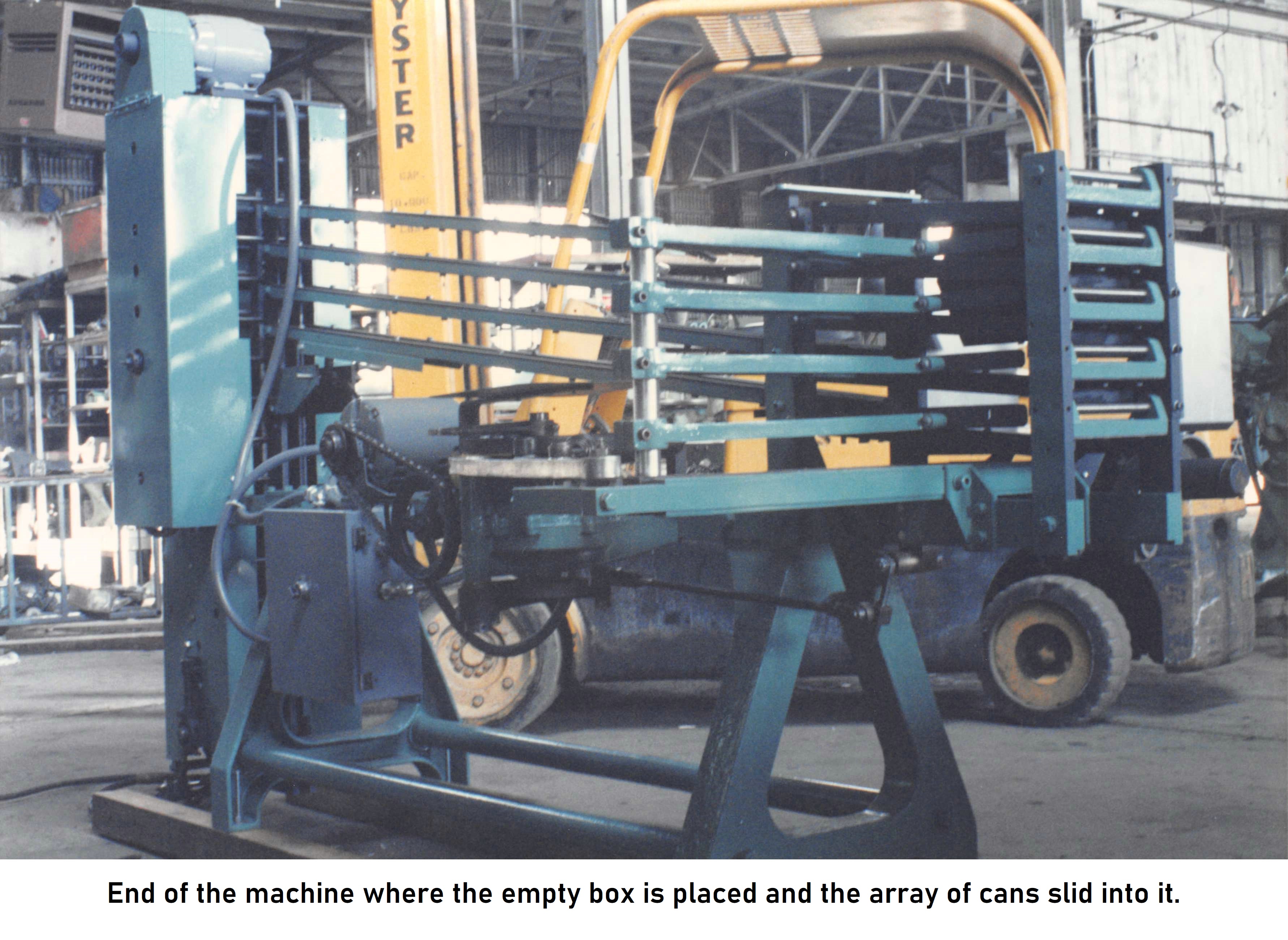
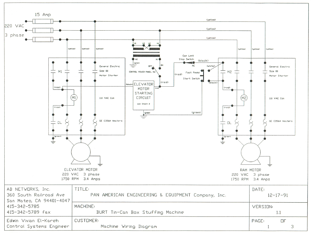
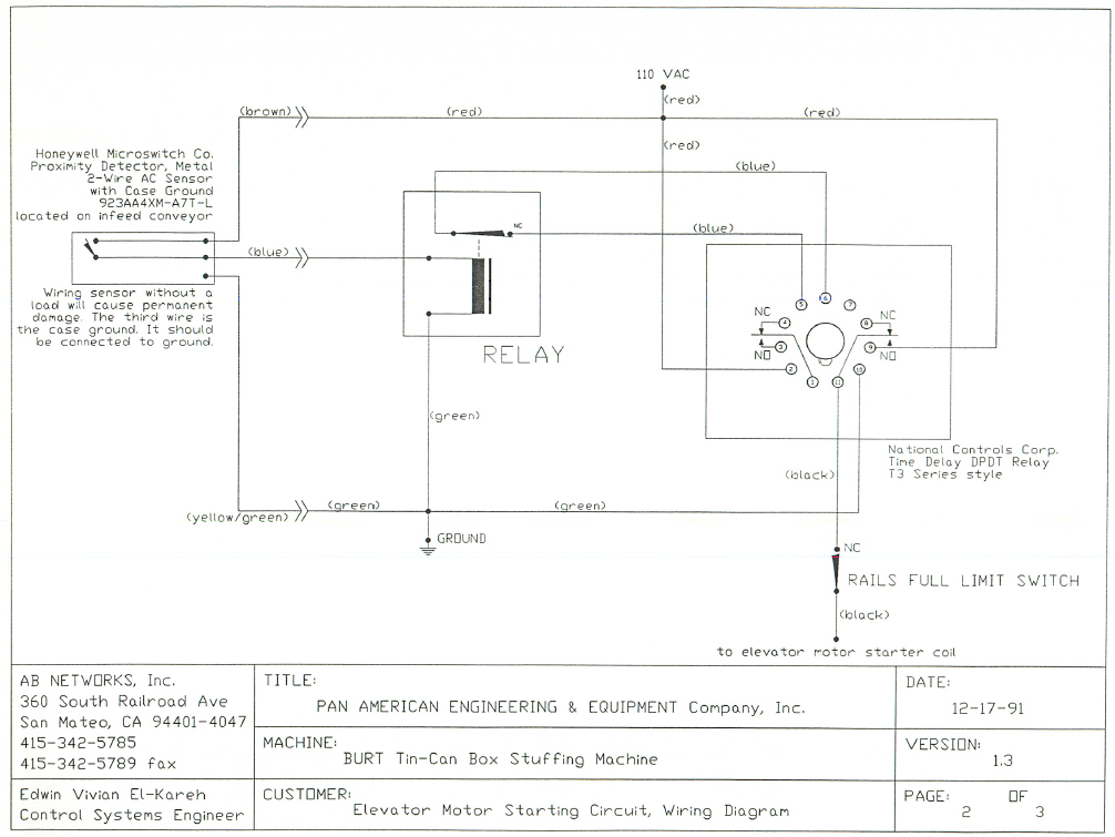
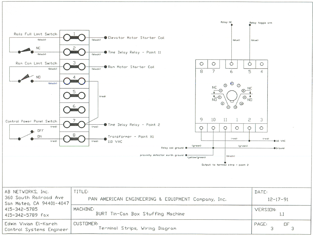
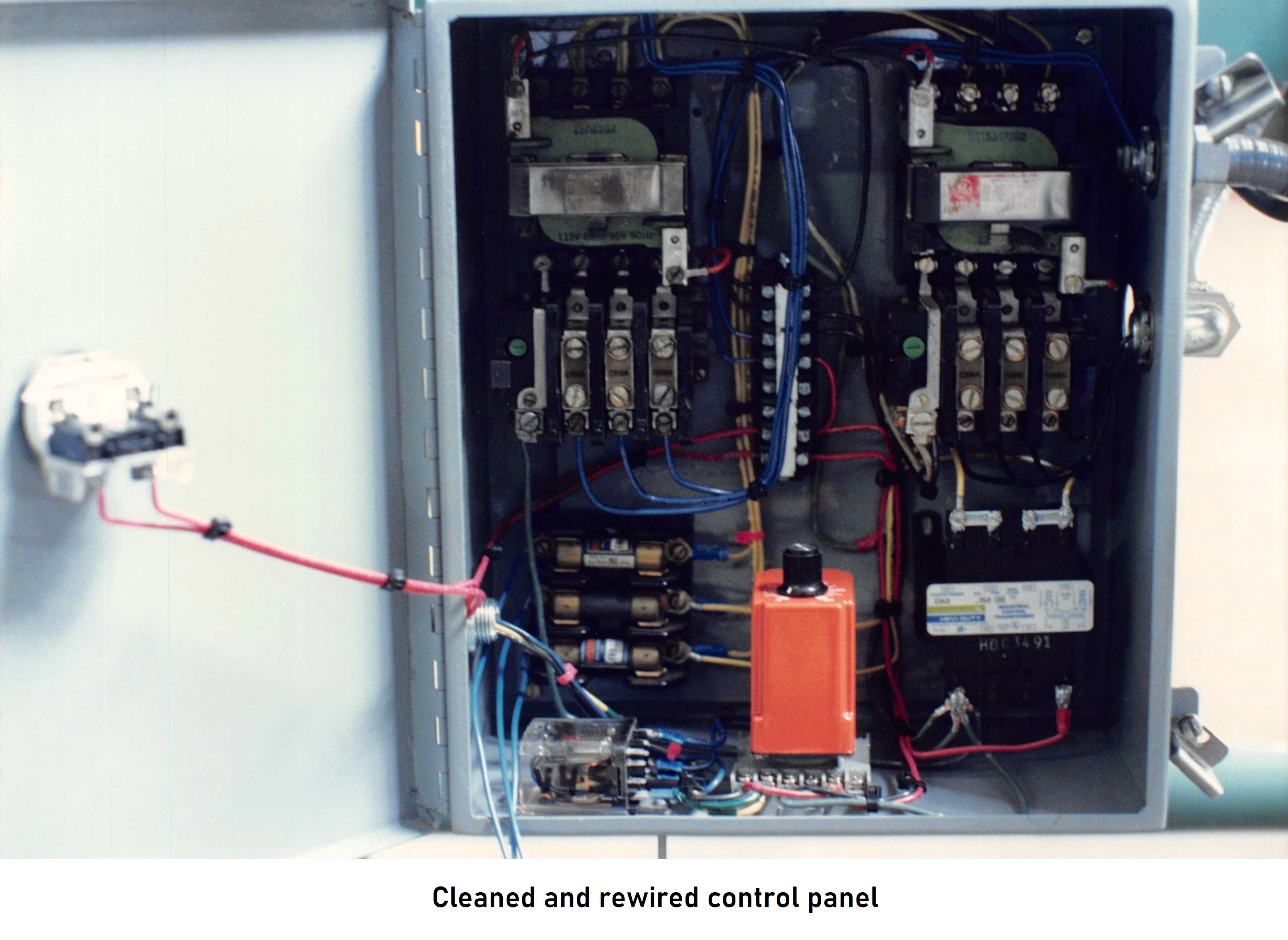
Machine Retrofit
Problem: Our team wanted to win business from a firm that refurbished food processing equipment and exported it to Argentina & Chile. There was plenty food equipment in the Santa Clara Valley before it became Silicon Valley, so the opportunity was large, The firm had many skilled mechanical technicians but no electrical expertise. They had mechanically refurbished a machine that stacked cans into cardboard boxes. However, the electrical panel was burnt out and needed rewiring and repair. There was also no documentation available for this old but still very mechanically sound machine.
Solution: We reverse engineered the wiring and then replaced it with new thick gauge wire. The coils on the contactors were fried and we replaced then with heavier duty versions. After testing our repairs we documented what we had done including providing data sheets for each of the components. The CAD department was backed up and unable to provide clean drawings in time for the machine's shipment. I used one of their AutoCAD stations after hours and completed the drawings in four hours. Even without any training on that specific software I made it work with just drawing lines, rectangles and circles.